| Last Modified: 01-30-2024 | 6.11:8.1.0 | Doc ID: RM1000000027LPX |
| Model Year Start: 2023 | Model: RAV4 | Prod Date Range: [10/2022 - ] |
| Title: BRAKE CONTROL / DYNAMIC CONTROL SYSTEMS: ELECTRONICALLY CONTROLLED BRAKE SYSTEM (w/o Vacuum Brake Booster): C050C12; Left Rear Wheel Speed Sensor Circuit Short to Battery; 2023 - 2024 MY RAV4 RAV4 HV [10/2022 - ] | ||
|
DTC |
C050C12 |
Left Rear Wheel Speed Sensor Circuit Short to Battery |
DESCRIPTION
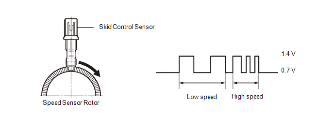
The skid control sensor detects wheel speed and sends the appropriate signals to the No. 2 skid control ECU (brake actuator assembly). These signals are used for brake control.
Speed sensor rotors have rows of alternating N and S magnetic poles, and their magnetic fields change when the rotors turn.
Each skid control sensor detects that magnetic change and sends a pulse signal to the No. 2 skid control ECU (brake actuator assembly).
HINT:
When the connectors between the skid control sensor and No. 2 skid control ECU (brake actuator assembly) are connected, the following waveform is output.
|
DTC No. |
Detection Item |
DTC Detection Condition |
Trouble Area |
MIL |
Note |
|---|---|---|---|---|---|
|
C050C12 |
Left Rear Wheel Speed Sensor Circuit Short to Battery |
The skid control sensor short signal is ON continuously for 0.5 seconds or more. |
|
Comes on |
|
MONITOR DESCRIPTION
The No. 2 skid control ECU (brake actuator assembly) monitors the current or power supply voltage of the speed sensor. If the power supply voltage or output current is excessively high, the MIL is illuminated and a DTC is stored.
MONITOR STRATEGY
|
Related DTCs |
C050F: Wheel speed sensor (RL) voltage circuit high |
|
Required Sensors/Components(Main) |
Speed sensor No. 2 skid control ECU (brake actuator assembly) |
|
Required Sensors/Components(Related) |
No. 2 skid control ECU (brake actuator assembly) |
|
Frequency of Operation |
Continuous |
|
Duration |
0.054 seconds: C050F (Case 2) 0.528 seconds: C050F (Case 1) |
|
MIL Operation |
Immediately |
|
Sequence of Operation |
None |
TYPICAL ENABLING CONDITIONS
Case 1
|
Monitor runs whenever the following DTCs are not stored |
C050D (Case 4): Wheel speed sensor (RL) range/performance C050E: Wheel speed sensor (RL) voltage circuit open C137D: Brake system voltage input out of range high C14E7: Wheel speed sensor (RL) voltage circuit low |
|
Both of the following conditions are met |
- |
|
Command to wheel speed sensor power supply |
On |
|
+BS voltage |
17.4 V or less |
Case 2
|
Monitor runs whenever the following DTCs are not stored |
None |
|
Power supply for wheel speed sensor |
Off |
TYPICAL MALFUNCTION THRESHOLDS
Case 1
|
Wheel speed sensor current |
0.034 A or more |
Case 2
|
Either of the following conditions is met |
- |
|
Power supply voltage for wheel speed sensor |
Higher than 4.1 V |
|
Wheel speed sensor current |
4 mA or less |
COMPONENT OPERATING RANGE
Case 1
|
Wheel speed sensor current |
Less than 0.034 A |
Case 2
|
All of the following conditions are met |
- |
|
Power supply for wheel speed sensor |
Off |
|
ECU state |
Pre main |
|
ABS pump motor fail (C052B, C052D, C052E, C055B) |
Not detected |
|
Brake system voltage fail (C143B, C143C) |
Not detected |
|
ABS hold solenoid fail (C0597) |
Not detected |
|
Wheel speed sensor fail (C0509, C0503, C0515, C050F) |
Not detected |
CONFIRMATION DRIVING PATTERN
NOTICE:
When performing the normal judgment procedure, make sure that the driver door is closed and is not opened at any time during the procedure.
HINT:
- After repair has been completed, clear the DTC and then check that the vehicle has returned to normal by performing the following All Readiness check procedure.
- When clearing the permanent DTCs, refer to the "CLEAR PERMANENT DTC" procedure.
- Connect the GTS to the DLC3.
- Turn the ignition switch to ON and turn the GTS on.
- Clear the DTCs (even if no DTCs are stored, perform the clear DTC procedure).
- Turn the ignition switch off.
- Turn the ignition switch to ON (READY) and turn the GTS on.
-
Wait for 2 seconds or more. [*]
HINT:
[*]: Normal judgment procedure.
The normal judgment procedure is used to complete DTC judgment and also used when clearing permanent DTCs.
- Enter the following menus: Chassis / Brake/EPB / Utility / All Readiness.
-
Check the DTC judgment result.
HINT:
- If the judgment result shows NORMAL, the system is normal.
- If the judgment result shows ABNORMAL, the system has a malfunction.
- If the judgment result shows INCOMPLETE, perform driving pattern again.
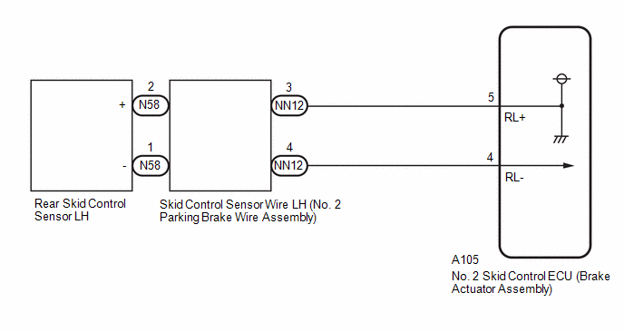
WIRING DIAGRAM
CAUTION / NOTICE / HINT
NOTICE:
-
After replacing the No. 2 skid control ECU (brake actuator assembly), perform "Calibration" after performing "Reset Memory".
Click here
![2022 - 2024 MY RAV4 RAV4 HV [12/2021 - ]; BRAKE CONTROL / DYNAMIC CONTROL SYSTEMS: ELECTRONICALLY CONTROLLED BRAKE SYSTEM (w/o Vacuum Brake Booster): UTILITY](/t3Portal/stylegraphics/info.gif)
-
After replacing or removing and installing a skid control sensor, perform Dealer Mode (Signal Check) inspection to confirm that the skid control sensors are operating correctly.
Click here
PROCEDURE
|
1. |
CHECK HARNESS AND CONNECTOR (SENSOR GROUND CIRCUIT) |
|
(a) Make sure that there is no looseness at the locking part and the connecting part of the connectors. OK: The connector is securely connected. |
|
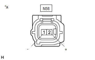
(b) Disconnect the N58 rear skid control sensor LH connector.
(c) Check both the connector case and the terminals for deformation and corrosion.
OK:
No deformation or corrosion.
(d) Turn the ignition switch to ON.
(e) Measure the voltage according to the value(s) in the table below.
Standard Voltage:
|
Tester Connection |
Condition |
Specified Condition |
|---|---|---|
|
N58-2 (+) - N58-1 (-) |
Ignition switch ON |
11 to 14 V |
| OK |

|
|

|
2. |
CHECK HARNESS AND CONNECTOR (SENSOR GROUND CIRCUIT) |
|
(a) Turn the ignition switch off. |
|

(b) Make sure that there is no looseness at the locking part and the connecting part of the connectors.
OK:
The connector is securely connected.
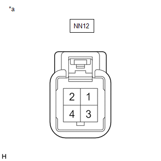
(c) Disconnect the NN12 skid control sensor wire LH (No. 2 parking brake wire assembly) connector.
(d) Check both the connector case and the terminals for deformation and corrosion.
OK:
No deformation or corrosion.
(e) Turn the ignition switch to ON.
(f) Measure the voltage according to the value(s) in the table below.
Standard Voltage:
|
Tester Connection |
Condition |
Specified Condition |
|---|---|---|
|
NN12-3 - NN12-4 |
Ignition switch ON |
11 to 14 V |
| OK |
|
REPLACE NO. 2 PARKING BRAKE WIRE ASSEMBLY |
|
|
3. |
CHECK HARNESS AND CONNECTOR (SENSOR GROUND CIRCUIT) |
|
(a) Turn the ignition switch off. |
|
(b) Make sure that there is no looseness at the locking part and the connecting part of the connectors.
OK:
The connector is securely connected.
(c) Disconnect the A105 No. 2 skid control ECU (brake actuator assembly) connector.
(d) Check both the connector case and the terminals for deformation and corrosion.
OK:
No deformation or corrosion.
(e) Measure the voltage according to the value(s) in the table below.
Standard Voltage:
|
Tester Connection |
Condition |
Specified Condition |
|---|---|---|
|
NN12-4 - Body ground |
Always |
Below 1.5 V |
| NG |
|
REPAIR OR REPLACE HARNESS OR CONNECTOR |
|
|
4. |
CHECK HARNESS AND CONNECTOR (NO. 2 PARKING BRAKE WIRE ASSEMBLY - BRAKE ACTUATOR ASSEMBLY) |
(a) Measure the resistance according to the value(s) in the table below.
Standard Resistance:
|
Tester Connection |
Condition |
Specified Condition |
|---|---|---|
|
NN12-3 or A105-5 (RL+) - NN12-4 or A105-4 (RL-) |
Always |
10 kΩ or higher |
| OK |
|
REPLACE BRAKE ACTUATOR ASSEMBLY
|
| NG |
|
REPAIR OR REPLACE HARNESS OR CONNECTOR |
|
|
|