| Last Modified: 01-30-2024 | 6.11:8.1.0 | Doc ID: RM1000000026S7W |
| Model Year Start: 2023 | Model: RAV4 | Prod Date Range: [10/2022 - ] |
| Title: CELLULAR COMMUNICATION: SAFETY CONNECT SYSTEM: B153711,B153713; Telephone Sub Antenna Circuit Short to Ground; 2023 - 2024 MY RAV4 RAV4 HV [10/2022 - ] | ||
|
DTC |
B153711 |
Telephone Sub Antenna Circuit Short to Ground |
|
DTC |
B153713 |
Telephone Sub Antenna Circuit Open |
DESCRIPTION
These DTCs are stored when a malfunction occurs in the telephone sub antenna circuit.
|
DTC No. |
Detection Item |
DTC Detection Condition |
Trouble Area |
DTC Output from |
Priority |
|---|---|---|---|---|---|
|
B153711 |
Telephone Sub Antenna Circuit Short to Ground |
Telephone antenna (sub) impedance (Ω) is lower than the malfunction threshold for 10 seconds or more when the ignition switch is ON (Short circuit) |
|
Telematics |
A |
|
B153713 |
Telephone Sub Antenna Circuit Open |
Telephone antenna (sub) impedance (Ω) is higher than the malfunction threshold for 10 seconds or more when the ignition switch is ON (Open circuit) |
|
Telematics |
A |
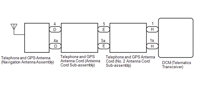
WIRING DIAGRAM

CAUTION / NOTICE / HINT
NOTICE:
Depending on the parts that are replaced during vehicle inspection or maintenance, performing initialization, registration or calibration may be needed. Refer to Precaution for Safety Connect System.
HINT:
Refer to "PARTS LOCATION" for the installation location of telephone antenna cord.
PROCEDURE
|
1. |
CLEAR DTC |
Pre-procedure1
(a) Turn the ignition switch to ON and wait for 10 seconds.
Procedure1
(b) Clear the DTCs.
Body Electrical > Telematics > Clear DTCs
Post-procedure1
(c) None
|
|
2. |
CHECK FOR DTC |
(a) Check for DTCs.
Body Electrical > Telematics > Trouble Codes
|
Result |
Proceed to |
|---|---|
|
DTCs are not output |
A |
|
DTCs are output |
B |
| A |

|
|
|
3. |
INSPECT TELEPHONE AND GPS ANTENNA (NAVIGATION ANTENNA ASSEMBLY) |
| NG |

|
REPLACE TELEPHONE AND GPS ANTENNA (NAVIGATION ANTENNA ASSEMBLY)
|
|
|
4. |
CHECK TELEPHONE AND GPS ANTENNA CORD (ANTENNA CORD SUB-ASSEMBLY) |
Pre-procedure1
|
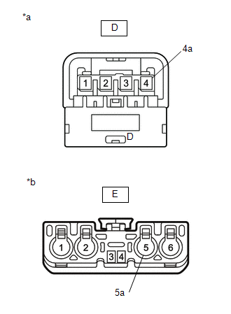
(a) Disconnect the telephone and GPS antenna cord (antenna cord sub-assembly) from the telephone and GPS antenna (navigation antenna assembly) connector. |
|
(b) Disconnect the telephone and GPS antenna cord (antenna cord sub-assembly) from the telephone and GPS antenna cord (No. 2 antenna cord sub-assembly) connector.
Procedure1
(c) Measure the resistance according to the value(s) in the table below.
Standard Resistance:
|
Tester Connection |
Condition |
Specified Condition |
|---|---|---|
|
D-4 - E-5 |
Always |
Below 1 Ω |
|
D-4a - E-5a |
Always |
Below 1 Ω |
|
D-4 or E-5 - Body ground |
Always |
10 kΩ or higher |
Post-procedure1
(d) None
| NG |

|
REPLACE TELEPHONE AND GPS ANTENNA CORD (ANTENNA CORD SUB-ASSEMBLY)
|
|
|
5. |
CHECK TELEPHONE AND GPS ANTENNA CORD (NO. 2 ANTENNA CORD SUB-ASSEMBLY) |
Pre-procedure1
|
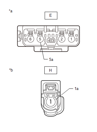
(a) Disconnect the telephone and GPS antenna cord (No. 2 antenna cord sub-assembly) from the telephone and GPS antenna cord (antenna cord sub-assembly) connector. |
|
(b) Disconnect the telephone and GPS antenna cord (No. 2 antenna cord sub-assembly) from the DCM (telematics transceiver).
Procedure1
(c) Measure the resistance according to the value(s) in the table below.
Standard Resistance:
|
Tester Connection |
Condition |
Specified Condition |
|---|---|---|
|
E-5 - H-1 |
Always |
Below 1 Ω |
|
E-5a - H-1a |
Always |
Below 1 Ω |
|
E-5 or H-1 - Body ground |
Always |
10 kΩ or higher |
Post-procedure1
(d) None
| NG |

|
REPLACE TELEPHONE AND GPS ANTENNA CORD (NO. 2 ANTENNA CORD SUB-ASSEMBLY) |
|
|
6. |
CHECK TELEPHONE AND GPS ANTENNA (NAVIGATION ANTENNA ASSEMBLY) |
Pre-procedure1
(a) Replace the telephone and GPS antenna (navigation antenna assembly) with a known good one and check if the same problem occurs again.
HINT:
Procedure1
(b) Clear the DTCs.
Body Electrical > Telematics > Clear DTCs
Post-procedure1
(c) None
|
|
7. |
CHECK FOR DTC |
(a) Recheck for DTCs and check that no DTCs are output.
Body Electrical > Telematics > Trouble Codes
|
Result |
Proceed to |
|---|---|
|
DTCs are not output |
A |
|
DTCs are output |
B |
| A |

|
END (TELEPHONE AND GPS ANTENNA [NAVIGATION ANTENNA ASSEMBLY] IS DEFECTIVE) |
|
|
8. |
REPLACE DCM (TELEMATICS TRANSCEIVER) |
(a) Replace the DCM (telematics transceiver).
HINT:
NOTICE:
- The ignition switch must be off.
- Do not exchange the DCM (telematics transceiver) with one from another vehicle.
| NEXT |

|
|
|
|
![2023 - 2024 MY RAV4 RAV4 HV [10/2022 - ]; CELLULAR COMMUNICATION: SAFETY CONNECT SYSTEM: PRECAUTION](/t3Portal/stylegraphics/info.gif)


