
- Turn the ignition switch to ON
- Sound is input to the telephone microphone assembly when the user is closer than 125 mm from the microphone case RH sound holes.
| Last Modified: 09-02-2025 | 6.11:8.1.0 | Doc ID: RM1000000026OM0 |
| Model Year Start: 2023 | Model: RAV4 | Prod Date Range: [10/2022 - ] |
| Title: AUDIO / VIDEO: AUDIO AND VISUAL SYSTEM: Microphone Circuit; 2023 - 2025 MY RAV4 RAV4 HV [10/2022 - ] | ||
|
Microphone Circuit |
DESCRIPTION
The radio and display receiver assembly, map light assembly and telephone microphone assembly are connected to each other using the microphone connection detection signal lines.
Using this circuit, the DCM (telematics transceiver) sends power to the map light assembly and telephone microphone assembly, and the map light assembly and telephone microphone assembly sends microphone signals to the radio and display receiver assembly via the DCM (telematics transceiver).
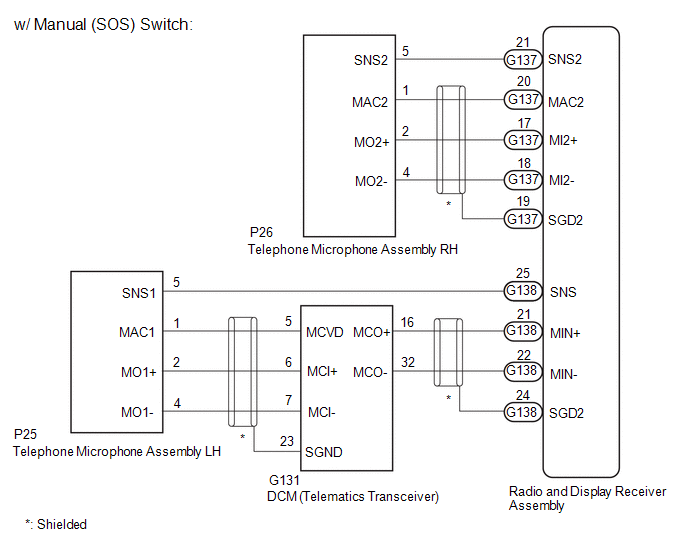
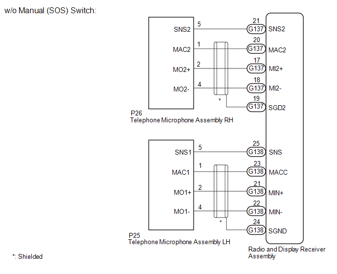
WIRING DIAGRAM
CAUTION / NOTICE / HINT
NOTICE:
-
Depending on the parts that are replaced during vehicle inspection or maintenance, performing initialization, registration or calibration may be needed. Refer to Precaution for Audio and Visual System.
Click here
![2023 - 2025 MY RAV4 RAV4 HV [10/2022 - ]; AUDIO / VIDEO: AUDIO AND VISUAL SYSTEM: PRECAUTION](/t3Portal/stylegraphics/info.gif)
-
Before replacing the DCM (telematics transceiver), refer to Registration.
Click here
PROCEDURE
PROCEDURE
|
1. |
CHECK MICROPHONE (OPERATION CHECK) |
|
(a) Enter diagnostic mode. Click here
|
|
(b) Select "Function Check/Setting" from the "Service Menu" screen.
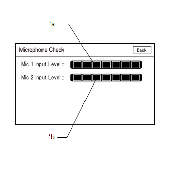
(c) Select "Microphone Check" from the "Function Check/Setting I" screen.
(d) Speak into each microphone assembly and check the microphone input level gauge display.
OK:
The microphone input levels of the gauge change in accordance with the voice.
|
Result |
Proceed to |
|---|---|
|
Microphone input levels change for microphone 1 and 2 |
A |
|
Microphone input level does not change for microphone 1 |
B |
|
Microphone input level does not change for microphone 2 |
C |
| A |

|
| B |
|
| C |
|
|
2. |
CHECK MODEL |
(a) Choose the model to be inspected.
|
Result |
Proceed to |
|---|---|
|
w/ Manual (SOS) Switch |
A |
|
w/o Manual (SOS) Switch |
B |
| B |
|
|
|
3. |
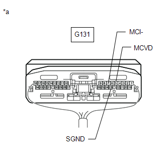
CHECK DCM (TELEMATICS TRANSCEIVER) (MICROPHONE POWER SOURCE AND BODY GROUND) |
HINT:
Measure the connector of the DCM (telematics transceiver) while it is connected.
|
(a) Measure the resistance according to the value(s) in the table below. Standard Resistance:
|
|
(b) Measure the voltage according to the value(s) in the table below.
Standard Voltage:
|
Tester Connection |
Switch Condition |
Specified Condition |
|---|---|---|
|
G131-5 (MCVD) - Body ground |
Ignition switch ON |
7.5 to 8.5 V |
| NG |
|
|
|
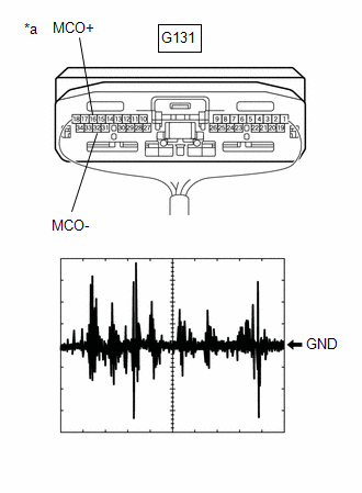
4. |
CHECK DCM (TELEMATICS TRANSCEIVER) (OUTPUT TO RADIO AND DISPLAY RECEIVER ASSEMBLY) |
HINT:
Measure the connector of the DCM (telematics transceiver) while it is connected.
|
(a) Using an oscilloscope, measure the waveform according to the condition(s) in the table below.
OK: The waveform is similar to that shown in the illustration. HINT:
|
|
|
Result |
Proceed to |
|---|---|
|
A waveform synchronized with voice signals is output |
A |
|
A waveform synchronized with voice signals is not output |
B |
| B |
|
|
|
5. |
CHECK HARNESS AND CONNECTOR (RADIO AND DISPLAY RECEIVER ASSEMBLY - DCM [TELEMATICS TRANSCEIVER]) |
(a) Disconnect the G138 radio and display receiver assembly connector.
(b) Disconnect the G131 DCM (telematics transceiver) connector.
(c) Measure the resistance according to the value(s) in the table below.
Standard Resistance:
|
Tester Connection |
Condition |
Specified Condition |
|---|---|---|
|
G138-21 (MIN+) - G131-16 (MCO+) |
Always |
Below 1 Ω |
|
G138-22 (MIN-) - G131-32 (MCO-) |
Always |
Below 1 Ω |
|
G138-21 (MIN+) - Body ground |
Always |
10 kΩ or higher |
|
G138-22 (MIN-) - Body ground |
Always |
10 kΩ or higher |
| OK |
|
| NG |
|
REPAIR OR REPLACE HARNESS OR CONNECTOR |
|
6. |
CHECK HARNESS AND CONNECTOR (RADIO AND DISPLAY RECEIVER ASSEMBLY - DCM [TELEMATICS TRANSCEIVER]) |
(a) Disconnect the G138 radio and display receiver assembly connector.
(b) Disconnect the G131 DCM (telematics transceiver) connector.
(c) Measure the resistance according to the value(s) in the table below.
Standard Resistance:
|
Tester Connection |
Condition |
Specified Condition |
|---|---|---|
|
G138-21 (MIN+) - G131-16 (MCO+) |
Always |
Below 1 Ω |
|
G138-22 (MIN-) - G131-32 (MCO-) |
Always |
Below 1 Ω |
|
G138-21 (MIN+) - Body ground |
Always |
10 kΩ or higher |
|
G138-22 (MIN-) - Body ground |
Always |
10 kΩ or higher |
| NG |
|
REPAIR OR REPLACE HARNESS OR CONNECTOR |
|
|
7. |
CHECK HARNESS AND CONNECTOR (DCM [TELEMATICS TRANSCEIVER] - TELEPHONE MICROPHONE ASSEMBLY RH) |
(a) Disconnect the G131 DCM (telematics transceiver) connector.
(b) Disconnect the P25 telephone microphone assembly RH connector.
(c) Measure the resistance according to the value(s) in the table below.
Standard Resistance:
|
Tester Connection |
Condition |
Specified Condition |
|---|---|---|
|
G131-5 (MCVD) - P25-1 (MAC1) |
Always |
Below 1 Ω |
|
G131-6 (MCI+) - P25-2 (MO1+) |
Always |
Below 1 Ω |
|
G131-7 (MCI-) - P25-4 (MO1-) |
Always |
Below 1 Ω |
|
G131-5 (MCVD) - Body ground |
Always |
10 kΩ or higher |
|
G131-6 (MCI+) - Body ground |
Always |
10 kΩ or higher |
|
G131-7 (MCI-) - Body ground |
Always |
10 kΩ or higher |
|
G131-23 (SGND) - Body ground |
Always |
10 kΩ or higher |
| NG |
|
REPAIR OR REPLACE HARNESS OR CONNECTOR |
|
|
8. |
CHECK HARNESS AND CONNECTOR (RADIO AND DISPLAY RECEIVER ASSEMBLY - TELEPHONE MICROPHONE ASSEMBLY LH) |
(a) Disconnect the G138 radio and display receiver assembly connector.
(b) Disconnect the P25 telephone microphone assembly LH connector.
(c) Measure the resistance according to the value(s) in the table below.
Standard Resistance:
|
Tester Connection |
Condition |
Specified Condition |
|---|---|---|
|
G138-25 (SNS) - P25-5 (SNS1) |
Always |
Below 1 Ω |
|
G138-25 (SNS) - Body ground |
Always |
10 kΩ or higher |
| NG |
|
REPAIR OR REPLACE HARNESS OR CONNECTOR |
|
|
9. |
CHECK TELEPHONE MICROPHONE ASSEMBLY LH (OUTPUT TO DCM [TELEMATICS TRANSCEIVER]) |
|
(a) Using an oscilloscope, measure the waveform according to the condition(s) in the table below.
OK: The waveform is similar to that shown in the illustration. HINT:
|
|
|
Result |
Proceed to |
|---|---|
|
A waveform synchronized with voice signals is output |
A |
|
A waveform synchronized with voice signals is not output |
B |
| A |
|
| B |
|
|
10. |
CHECK HARNESS AND CONNECTOR (DCM [TELEMATICS TRANSCEIVER] - TELEPHONE MICROPHONE ASSEMBLY LH) |
(a) Disconnect the G131 DCM (telematics transceiver) connector.
(b) Disconnect the P25 telephone microphone assembly LH connector.
(c) Measure the resistance according to the value(s) in the table below.
Standard Resistance:
|
Tester Connection |
Condition |
Specified Condition |
|---|---|---|
|
G131-5 (MCVD) - P25-1 (MAC1) |
Always |
Below 1 Ω |
|
G131-6 (MCI+) - P25-2 (MO1+) |
Always |
Below 1 Ω |
|
G131-7 (MCI-) - P25-4 (MO1-) |
Always |
Below 1 Ω |
|
G131-5 (MCVD) or P25-1 (MAC1) - Body ground |
Always |
10 kΩ or higher |
|
G131-6 (MCI+) or P25-2 (MO1+) - Body ground |
Always |
10 kΩ or higher |
|
G131-7 (MCI-) or P25-4 (MO1-) - Body ground |
Always |
10 kΩ or higher |
| NG |
|
REPAIR OR REPLACE HARNESS OR CONNECTOR |
|
|
11. |
CHECK HARNESS AND CONNECTOR (RADIO AND DISPLAY RECEIVER ASSEMBLY - DCM [TELEMATICS TRANSCEIVER]) |
(a) Disconnect the G138 radio and display receiver assembly connector.
(b) Disconnect the G131 DCM (telematics transceiver) connector.
(c) Measure the resistance according to the value(s) in the table below.
Standard Resistance:
|
Tester Connection |
Condition |
Specified Condition |
|---|---|---|
|
G138-21 (MIN+) - G131-16 (MCO+) |
Always |
Below 1 Ω |
|
G138-22 (MIN-) - G131-32 (MCO-) |
Always |
Below 1 Ω |
|
G138-21 (MIN+) or G131-16 (MCO+) - Body ground |
Always |
10 kΩ or higher |
|
G138-22 (MIN-) or G131-32 (MCO-) - Body ground |
Always |
10 kΩ or higher |
| OK |
|
| NG |
|
REPAIR OR REPLACE HARNESS OR CONNECTOR |
|
12. |
CHECK HARNESS AND CONNECTOR (RADIO AND DISPLAY RECEIVER ASSEMBLY - TELEPHONE MICROPHONE ASSEMBLY LH) |
(a) Disconnect the G138 radio and display receiver assembly connector.
(b) Disconnect the P25 telephone microphone assembly LH connector.
(c) Measure the resistance according to the value(s) in the table below.
Standard Resistance:
|
Tester Connection |
Condition |
Specified Condition |
|---|---|---|
|
G138-25 (SNS) - P25-5 (SNS1) |
Always |
Below 1 Ω |
|
G138-23 (MACC) - P25-1 (MAC1) |
Always |
Below 1 Ω |
|
G138-21 (MIN+) - P25-2 (MO1+) |
Always |
Below 1 Ω |
|
G138-22 (MIN-) - P25-4 (MO1-) |
Always |
Below 1 Ω |
|
G138-25 (SNS) - Body ground |
Always |
10 kΩ or higher |
|
G138-23 (MACC) - Body ground |
Always |
10 kΩ or higher |
|
G138-21 (MIN+) - Body ground |
Always |
10 kΩ or higher |
|
G138-22 (MIN-) - Body ground |
Always |
10 kΩ or higher |
|
G138-24 (SGND) - Body ground |
Always |
10 kΩ or higher |
| NG |
|
REPAIR OR REPLACE HARNESS OR CONNECTOR |
|
|
13. |
CHECK RADIO AND DISPLAY RECEIVER ASSEMBLY (MACC, MIN-) |
(a) With the G138 radio and display receiver assembly connector connected, disconnect the P25 telephone microphone assembly LH connector.
(b) Measure the resistance according to the value(s) in the table below.
Standard Resistance:
|
Tester Connection |
Condition |
Specified Condition |
|---|---|---|
|
P25-4 (MO1-) - Body ground |
Always |
Below 1 Ω |
(c) Measure the voltage according to the value(s) in the table below.
Standard Voltage:
|
Tester Connection |
Switch Condition |
Specified Condition |
|---|---|---|
|
P25-1 (MAC1) - Body ground |
Ignition switch ON |
7.5 to 8.5 V |
| NG |
|
|
|
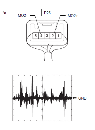
14. |
CHECK TELEPHONE MICROPHONE ASSEMBLY (OUTPUT TO RADIO AND DISPLAY RECEIVER ASSEMBLY) |

|
*a |
Component with harness connected (Telephone Microphone Assembly LH) |
(a) Using an oscilloscope, measure the waveform according to the condition(s) in the table below.
|
Item |
Condition |
|---|---|
|
Tester Connection |
P25-2 (MO1+) - P25-4 (MO1-) |
|
Tool setting |
50 mV/DIV., 500 ms/DIV. |
|
Vehicle condition |
|
OK:
The waveform is similar to that shown in the illustration.
HINT:
- The oscilloscope waveform shown in the illustration is an example for reference only.
- In order to ensure that a consistent sound level is input to the microphone, use a digital voice recorder, etc., to play back sound in the same location with respect to the microphone.
|
Result |
Proceed to |
|---|---|
|
A waveform synchronized with voice signals is output |
A |
|
A waveform synchronized with voice signals is not output |
B |
| A |
|
| B |
|
|
15. |
CHECK HARNESS AND CONNECTOR (RADIO AND DISPLAY RECEIVER ASSEMBLY - TELEPHONE MICROPHONE ASSEMBLY LH) |
(a) Disconnect the G138 radio and display receiver assembly connector.
(b) Disconnect the P25 telephone microphone assembly LH connector.
(c) Measure the resistance according to the value(s) in the table below.
Standard Resistance:
|
Tester Connection |
Condition |
Specified Condition |
|---|---|---|
|
G138-25 (SNS) - P25-5 (SNS1) |
Always |
Below 1 Ω |
|
G138-23 (MACC) - P25-1 (MAC1) |
Always |
Below 1 Ω |
|
G138-21 (MIN+) - P25-2 (MO1+) |
Always |
Below 1 Ω |
|
G138-22 (MIN-) - P25-4 (MO1-) |
Always |
Below 1 Ω |
|
G138-25 (SNS) - Body ground |
Always |
10 kΩ or higher |
|
G138-23 (MACC) - Body ground |
Always |
10 kΩ or higher |
|
G138-21 (MIN+) - Body ground |
Always |
10 kΩ or higher |
|
G138-22 (MIN-) - Body ground |
Always |
10 kΩ or higher |
|
G138-24 (SGND) - Body ground |
Always |
10 kΩ or higher |
| NG |
|
REPAIR OR REPLACE HARNESS OR CONNECTOR |
|
|
16. |
CHECK RADIO AND DISPLAY RECEIVER ASSEMBLY (MACC, MIN-) |
(a) With the G138 radio and display receiver assembly connector connected, disconnect the P25 telephone microphone assembly LH connector.
(b) Measure the resistance according to the value(s) in the table below.
Standard Resistance:
|
Tester Connection |
Condition |
Specified Condition |
|---|---|---|
|
P25-4 (MO1-) - Body ground |
Always |
Below 1 Ω |
(c) Measure the voltage according to the value(s) in the table below.
Standard Voltage:
|
Tester Connection |
Switch Condition |
Specified Condition |
|---|---|---|
|
P25-1 (MAC1) - Body ground |
Ignition switch ON |
7.5 to 8.5 V |
| NG |
|
|
|
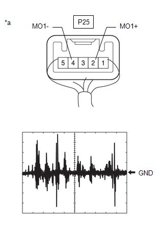
17. |
CHECK TELEPHONE MICROPHONE ASSEMBLY LH (OUTPUT TO RADIO AND DISPLAY RECEIVER ASSEMBLY) |
|
*a |
Component with harness connected (Telephone Microphone Assembly LH) |
(a) Using an oscilloscope, measure the waveform according to the condition(s) in the table below.
|
Item |
Condition |
|---|---|
|
Tester Connection |
P25-2 (MO1+) - P25-4 (MO1-) |
|
Tool setting |
50 mV/DIV., 500 ms/DIV. |
|
Vehicle condition |
|
OK:
The waveform is similar to that shown in the illustration.
HINT:
- The oscilloscope waveform shown in the illustration is an example for reference only.
- In order to ensure that a consistent sound level is input to the microphone, use a digital voice recorder, etc., to play back sound in the same location with respect to the microphone.
|
Result |
Proceed to |
|---|---|
|
A waveform synchronized with voice signals is output |
A |
|
A waveform synchronized with voice signals is not output |
B |
| A |
|
| B |
|
|
|
|