| Last Modified: 01-30-2024 | 6.11:8.1.0 | Doc ID: RM1000000026OLS |
| Model Year Start: 2023 | Model: RAV4 | Prod Date Range: [10/2022 - ] |
| Title: AUDIO / VIDEO: AUDIO AND VISUAL SYSTEM: Satellite Radio Broadcast cannot be Received; 2023 - 2024 MY RAV4 RAV4 HV [10/2022 - ] | ||
|
Satellite Radio Broadcast cannot be Received |
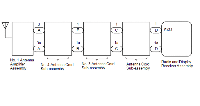
WIRING DIAGRAM
CAUTION / NOTICE / HINT
NOTICE:
Some satellite radio broadcasts require payment. A contract must be made between a satellite radio company and the user. If the contract expires, it will not be possible to listen to the broadcast.
HINT:
Depending on the parts that are replaced during vehicle inspection or maintenance, performing initialization, registration or calibration may be needed. Refer to Precaution for Audio and Visual System.
PROCEDURE
|
1. |
CHECK SURROUNDINGS |
(a) Check if the vehicle is in an environment where reception is difficult due to something blocking the area above the vehicle.
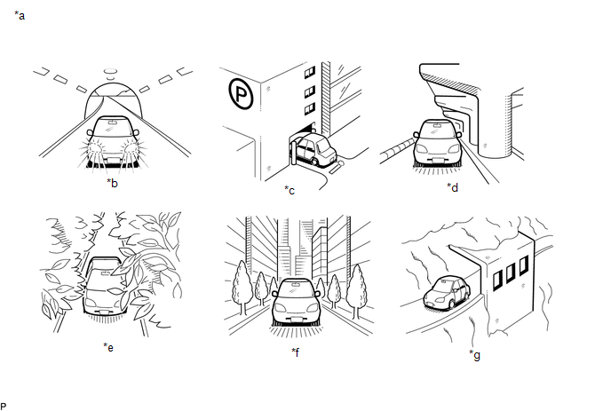
|
*a |
Example |
*b |
In a tunnel |
|
*c |
In a building |
*d |
Under an overpass |
|
*e |
In a forest or on tree-lined path |
*f |
Between tall buildings |
|
*g |
Under a cliff or overhang |
- |
- |
HINT:
If the area above the vehicle is blocked, such as when in a building or tunnel, reception may not be possible.
OK:
Area above vehicle is not blocked.
| NG |

|
END (MOVE VEHICLE TO LOCATION WHERE RECEPTION IS BETTER) |
|
|
2. |
CHECK RADIO AND DISPLAY RECEIVER ASSEMBLY |
(a) Check if CH001 (free broadcast) can be received.
OK:
CH001 can be received.
| NG |

|
|
|
3. |
CHECK DISPLAY SETTING |
(a) Check the display screen.
|
Result |
Proceed to |
|---|---|
|
"SAT Ch Unauth" is displayed. |
A |
|
"-----" is displayed. |
B |
|
None of the displays above are shown. |
C |
| B |

|
THERE IS NO SONG/PROGRAM TITLE OR ARTIST NAME/FEATURE ASSOCIATED WITH CHANNEL AT THAT TIME |
| C |

|
|
|
4. |
CHECK CONTRACT CONDITIONS |
(a) Check if the pay-type contract has been extended, or if the contract period has ended.
OK:
Pay-type contract is valid.
| NG |

|
TO RECEIVE PAY-TYPE BROADCASTS, CONTRACT MUST BE MADE WITH SATELLITE RADIO COMPANY |
|
|
5. |
PERFORM ACTIVATION REFRESH |
(a) Perform activation refresh by referring to the satellite radio company website (http://www.siriusxm.com).
OK:
Malfunction disappears.
HINT:
The SiriusXM radio ID that is necessary to perform activation refresh is displayed when CH000 is selected on the satellite radio.
| OK |

|
END |
| NG |

|
PROCEED TO NEXT SUSPECTED AREA SHOWN IN PROBLEM SYMPTOMS TABLE |
|
6. |
CHECK DISPLAY |
(a) Check the display screen.
|
Result |
Proceed to |
|---|---|
|
"SAT Ck Antenna" is displayed. |
A |
|
"SAT No Signal" is displayed. |
B |
|
"Loading" is displayed. |
|
|
"SAT Ch Off Air" is displayed. |
C |
|
After "SAT Ch Unavail" is displayed, display automatically switches to CH001. |
D |
|
None of the displays above are shown. |
E |
| B |

|
END (MOVE VEHICLE TO LOCATION WHERE RECEPTION IS BETTER) |
| C |

|
CHANNEL IS CURRENTLY NOT BEING BROADCASTED. BROADCAST CAN BE LISTENED TO OR VIEWED WHEN IT IS BACK ON AIR. (CHECK WITH RADIO STATION) |
| D |

|
CHANNEL BROADCAST HAS ENDED (CHECK WITH RADIO STATION) |
| E |

|
|
|
7. |
CHECK NO. 4 ANTENNA CORD SUB-ASSEMBLY |
|
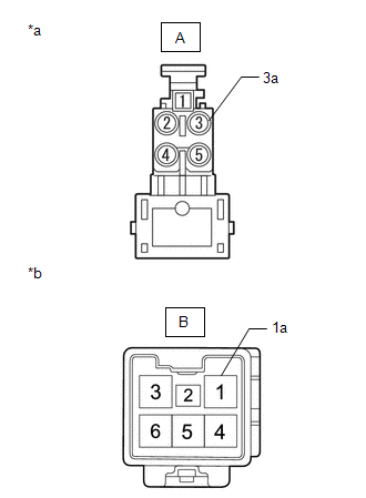
(a) Disconnect the antenna connector from the No. 1 antenna amplifier assembly. |
|
(b) Disconnect the antenna connector from the No. 3 antenna cord sub-assembly.
(c) Measure the resistance according to the value(s) in the table below.
Standard Resistance:
|
Tester Connection |
Condition |
Specified Condition |
|---|---|---|
|
A-3 - B-1 |
Always |
Below 1 Ω |
|
A-3a - B-1a |
Always |
Below 1 Ω |
|
A-3 - Body ground |
Always |
10 kΩ or higher |
| NG |

|
|
|
8. |
CHECK NO. 3 ANTENNA CORD SUB-ASSEMBLY |
|
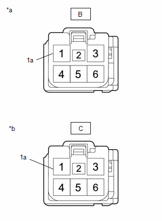
(a) Disconnect the antenna connector from the No. 4 antenna cord sub-assembly. |
|
(b) Disconnect the antenna connector from the antenna cord sub-assembly.
(c) Measure the resistance according to the value(s) in the table below.
Standard Resistance:
|
Tester Connection |
Condition |
Specified Condition |
|---|---|---|
|
B-1 - C-1 |
Always |
Below 1 Ω |
|
B-1a - C-1a |
Always |
Below 1 Ω |
|
B-1 - Body ground |
Always |
10 kΩ or higher |
| NG |

|
|
|
9. |
CHECK ANTENNA CORD SUB-ASSEMBLY |
|
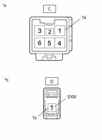
(a) Disconnect the antenna connector from the No. 3 antenna cord sub-assembly. |
|
(b) Disconnect the antenna connector from the radio and display receiver assembly.
(c) Measure the resistance according to the value(s) in the table below.
Standard Resistance:
|
Tester Connection |
Condition |
Specified Condition |
|---|---|---|
|
C-1 - D-1 (SXM) |
Always |
Below 1 Ω |
|
C-1a - D-1a |
Always |
Below 1 Ω |
|
C-1 - Body ground |
Always |
10 kΩ or higher |
| NG |

|
|
|
10. |
REPLACE NO. 1 AMPLIFIER ANTENNA ASSEMBLY |
(a) Replace the roof antenna assembly with a new or known good one.
(b) Clear the DTCs.
Body Electrical > Navigation System > Clear DTCs
(c) Check for DTCs.
Body Electrical > Navigation System > Trouble Codes
OK:
No DTCs are output.
| OK |

|
END (NO. 1 AMPLIFIER ANTENNA ASSEMBLY IS DEFECTIVE) |
| NG |

|
PROCEED TO NEXT SUSPECTED AREA SHOWN IN PROBLEM SYMPTOMS TABLE |
|
11. |
CHECK CURRENTLY SELECTED CHANNEL |
(a) Check if CH000 is currently selected.
OK:
CH000 is selected.
| OK |

|
END (CH000 HAS NO SOUND. SELECT ANOTHER CHANNEL.) |
| NG |

|
PROCEED TO NEXT SUSPECTED AREA SHOWN IN PROBLEM SYMPTOMS TABLE |
|
|
|
![2023 - 2024 MY RAV4 RAV4 HV [10/2022 - ]; AUDIO / VIDEO: AUDIO AND VISUAL SYSTEM: PRECAUTION](/t3Portal/stylegraphics/info.gif)

