| Last Modified: 01-30-2024 | 6.11:8.1.0 | Doc ID: RM1000000026OLQ |
| Model Year Start: 2023 | Model: RAV4 | Prod Date Range: [10/2022 - ] |
| Title: AUDIO / VIDEO: AUDIO AND VISUAL SYSTEM: C162287; Rear Camera Image Signal Missing Message; 2023 - 2024 MY RAV4 RAV4 HV [10/2022 - ] | ||
|
DTC |
C162287 |
Rear Camera Image Signal Missing Message |
DESCRIPTION
This DTC is stored if the radio and display receiver assembly judges that the signal from the rear television camera assembly is not normal.
|
DTC No. |
Detection Item |
DTC Detection Condition |
Trouble Area |
DTC Output from |
Priority |
|---|---|---|---|---|---|
|
C162287 |
Rear Camera Image Signal Missing Message |
When the ignition switch is ON, a malfunction is detected in the image signal of the rear television camera assembly (2 trip detection logic) |
|
Navigation System |
B |
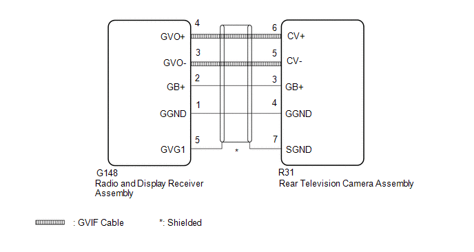
WIRING DIAGRAM
CAUTION / NOTICE / HINT
NOTICE:
-
Depending on the parts that are replaced or operations that are performed during vehicle inspection or maintenance, calibration of other systems as well as the parking assist monitor system may be needed.
Click here
![2023 - 2024 MY RAV4 RAV4 HV [10/2022 - ]; PARK ASSIST / MONITORING: PARKING ASSIST MONITOR SYSTEM: CALIBRATION](/t3Portal/stylegraphics/info.gif)
-
Depending on the parts that are replaced during vehicle inspection or maintenance, performing initialization, registration or calibration may be needed.
Click here
PROCEDURE
|
1. |
CHECK PARKING ASSIST MONITOR SYSTEM |
(a) Check if the parking assist monitor system is malfunctioning.
Click here
|
Result |
Proceed to |
|---|---|
|
Malfunction does not occur |
A |
|
Malfunction occurs |
B |
| B |

|
|

|
2. |
CHECK HARNESS AND CONNECTOR (RADIO AND DISPLAY RECEIVER ASSEMBLY - REAR TELEVISION CAMERA ASSEMBLY) |
Pre-procedure1
(a) Disconnect the G148 radio and display receiver assembly connector.
(b) Disconnect the R31 rear television camera assembly connector.
Procedure1
(c) Measure the resistance according to the value(s) in the table below.
Standard Resistance:
|
Tester Connection |
Condition |
Specified Condition |
|---|---|---|
|
R31-6 (CV+) - G148-3 (GVO+) |
Always |
Below 1 Ω |
|
R31-5 (CV-) - G148-4 (GVO-) |
Always |
Below 1 Ω |
|
R31-7 (SGND) - G148-5 (GVG1) |
Always |
Below 1 Ω |
|
R31-4 (GB+) - G148-2 (GB+) |
Always |
Below 1 Ω |
|
R31-3 (GGND) - G148-1 (GGND) |
Always |
Below 1 Ω |
|
R31-6 (CV+) - Body ground |
Always |
10 kΩ or higher |
|
R31-5 (CV-) - Body ground |
Always |
10 kΩ or higher |
|
R31-7 (SGND) - Body ground |
Always |
10 kΩ or higher |
|
R31-4 (GB+) - Body ground |
Always |
10 kΩ or higher |
|
R31-3 (GGND) - Body ground |
Always |
10 kΩ or higher |
Post-procedure1
(d) None
| OK |
|
| NG |
|
REPAIR OR REPLACE HARNESS OR CONNECTOR |
|
|
|