| Last Modified: 01-30-2024 | 6.11:8.1.0 | Doc ID: RM1000000026OLG |
| Model Year Start: 2023 | Model: RAV4 | Prod Date Range: [10/2022 - ] |
| Title: AUDIO / VIDEO: AUDIO AND VISUAL SYSTEM: B157913; Voice Recognition Microphone1 Circuit Open; 2023 - 2024 MY RAV4 RAV4 HV [10/2022 - ] | ||
|
DTC |
B157913 |
Voice Recognition Microphone1 Circuit Open |
DESCRIPTION
The telephone microphone assembly LH is connected to the radio and display receiver assembly via voice recognition microphone 1 signal detection line.
This DTC is stored when the radio and display receiver assembly detects disconnection of telephone microphone assembly LH.
|
DTC No. |
Detection Item |
DTC Detection Condition |
Trouble Area |
DTC Output from |
Priority |
|---|---|---|---|---|---|
|
B157913 |
Voice Recognition Microphone1 Circuit Open |
Voice recognition microphone LH terminal (SNS1) disconnected (2 trip detection logic) |
|
Navigation System |
A |
- *: w/ Manual (SOS) Switch
WIRING DIAGRAM
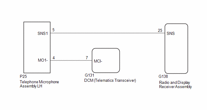
w/ Manual (SOS) Switch:
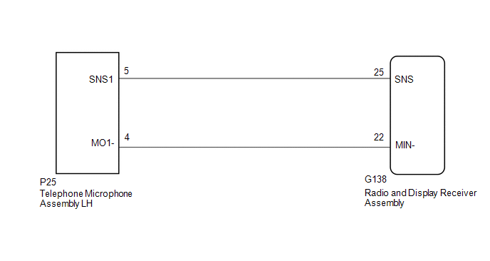
w/o Manual (SOS) Switch:
CAUTION / NOTICE / HINT
NOTICE:
- When replacing the DCM (telematics transceiver), make sure to replace it with a new one. (w/ Manual [SOS] Switch)
-
Depending on the parts that are replaced during vehicle inspection or maintenance, performing initialization, registration or calibration may be needed.
Click here
![2023 - 2024 MY RAV4 RAV4 HV [10/2022 - ]; AUDIO / VIDEO: AUDIO AND VISUAL SYSTEM: PRECAUTION](/t3Portal/stylegraphics/info.gif)
PROCEDURE
|
1. |
CHECK VEHICLE TYPE |
|
Result |
Proceed to |
|---|---|
|
w/ Manual (SOS) Switch |
A |
|
w/o Manual (SOS) Switch |
B |
| B |

|
|

|
2. |
CHECK HARNESS AND CONNECTOR (RADIO AND DISPLAY RECEIVER ASSEMBLY - TELEPHONE MICROPHONE ASSEMBLY LH) |
Pre-procedure1
(a) Disconnect the G138 radio and display receiver assembly connector.
(b) Disconnect the P25 telephone microphone assembly LH connector.
Procedure1
(c) Measure the resistance according to the value(s) in the table below.
Standard Resistance:
|
Tester Connection |
Condition |
Specified Condition |
|---|---|---|
|
G138-25 (SNS) - P25-5 (SNS1) |
Always |
Below 1 Ω |
|
G138-25 (SNS) - Body ground |
Always |
10 kΩ or higher |
Post-procedure1
(d) None
| NG |
|
REPAIR OR REPLACE HARNESS OR CONNECTOR |
|
|
3. |
CHECK HARNESS AND CONNECTOR (DCM [TELEMATICS TRANSCEIVER] - TELEPHONE MICROPHONE ASSEMBLY LH) |
Pre-procedure1
(a) Disconnect the I36 DCM (telematics transceiver) connector.
(b) Disconnect the S4 telephone microphone assembly LH connector.
Procedure1
(c) Measure the resistance according to the value(s) in the table below.
Standard Resistance:
|
Tester Connection |
Condition |
Specified Condition |
|---|---|---|
|
I36-7 (MCI-) - S4-4 (MO1-) |
Always |
Below 1 Ω |
|
I36-7 (MCI-) - Body ground |
Always |
10 kΩ or higher |
Post-procedure1
(d) None
| NG |
|
|
|
4. |
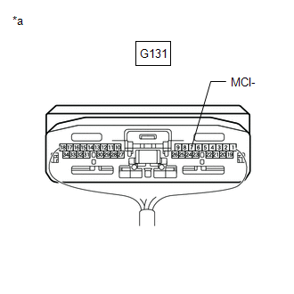
CHECK DCM (TELEMATICS TRANSCEIVER) (MCI-) |
Pre-procedure1
|
(a) Remove the DCM (telematics transceiver) with the connector(s) still connected. Click here
|
|
Procedure1
(b) Measure the resistance according to the value(s) in the table below.
Standard Resistance:
|
Tester Connection |
Condition |
Specified Condition |
|---|---|---|
|
G131-7 (MCI-) - Body ground |
Always |
Below 1 Ω |
Post-procedure1
(c) None
| OK |
|
| NG |
|
|
5. |
CHECK HARNESS AND CONNECTOR (RADIO AND DISPLAY RECEIVER ASSEMBLY - TELEPHONE MICROPHONE ASSEMBLY LH) |
Pre-procedure1
(a) Disconnect the G138 radio and display receiver assembly connector.
(b) Disconnect the P25 telephone microphone assembly LH connector.
Procedure1
(c) Measure the resistance according to the value(s) in the table below.
Standard Resistance:
|
Tester Connection |
Condition |
Specified Condition |
|---|---|---|
|
G138-25 (SNS) - P25-5 (SNS1) |
Always |
Below 1 Ω |
|
G138-22 (MIN-) - P25-4 (MO1-) |
Always |
Below 1 Ω |
|
G138-25 (SNS) - Body ground |
Always |
10 kΩ or higher |
|
G138-22 (MIN-) - Body ground |
Always |
10 kΩ or higher |
Post-procedure1
(d) None
| NG |
|
REPAIR OR REPLACE HARNESS OR CONNECTOR |
|
|
6. |
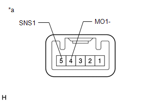
INSPECT TELEPHONE MICROPHONE ASSEMBLY LH (SNS1, MO1-) |
Pre-procedure1
|
(a) Remove the telephone microphone assembly LH. |
|
Procedure1
(b) Measure the resistance according to the value(s) in the table below.
Standard Resistance:
|
Tester Connection |
Condition |
Specified Condition |
|---|---|---|
|
5 (SNS1) - 4 (MO1-) |
Always |
Below 1 Ω |
Post-procedure1
(c) None
| OK |
|
| NG |
|
|
|
|