| Last Modified: 01-30-2024 | 6.11:8.1.0 | Doc ID: RM1000000026O6K |
| Model Year Start: 2023 | Model: RAV4 | Prod Date Range: [10/2022 - ] |
| Title: METER / GAUGE / DISPLAY: METER / GAUGE SYSTEM: B132187; Lost Communication with EMV Missing Message; 2023 - 2024 MY RAV4 RAV4 HV [10/2022 - ] | ||
|
DTC |
B132187 |
Lost Communication with EMV Missing Message |
DESCRIPTION
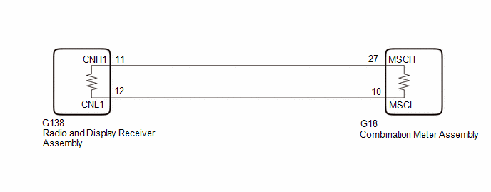
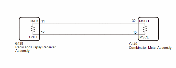
The combination meter assembly and radio and display receiver assembly communicate via local bus communication. This allows audio and visual system information to be displayed on the multi-information display. This DTC is stored when a communication error occurs between the radio and display receiver assembly and combination meter assembly.
|
DTC No. |
Detection Item |
DTC Detection Condition |
Trouble Area |
|---|---|---|---|
|
B132187 |
Lost Communication with EMV Missing Message |
Diagnosis Condition:
Malfunction Status:
Malfunction Time:
|
|
WIRING DIAGRAM
for 7 Inch Multi-information Display Type

for 12.3 Inch Multi-information Display Type

CAUTION / NOTICE / HINT
NOTICE:
- When replacing the combination meter assembly, always replace it with a new one. If a combination meter assembly which was installed to another vehicle is used, the information stored in it will not match the information from the vehicle and a DTC may be stored.
-
When replacing the radio and display receiver assembly, always replace it with a new one. If a radio and display receiver assembly which was installed to another vehicle is used, the following may occur:
- A communication malfunction DTC may be stored.
- The radio and display receiver assembly may not operate normally.
PROCEDURE
|
1. |
CHECK CAN MAIN WIRE (COMBINATION METER ASSEMBLY CAN MAIN WIRE) |
(a) Disconnect the cable from the negative (-) auxiliary battery terminal.
(b) Disconnect the G18*1 or G140*2 combination meter assembly connector.
- *1: for 7 Inch Multi-information Display Type
- *2: for 12.3 Inch Multi-information Display Type
(c) Measure the resistance according to the value(s) in the table below.
Standard Resistance:
for 7 Inch Multi-information Display Type
|
Tester Connection |
Condition |
Specified Condition |
|---|---|---|
|
G18-27 (MSCH) - G18-10 (MSCL) |
Cable disconnected from negative (-) auxiliary battery terminal |
108 to 132 Ω |
|
G18-27 (MSCH) - G114-4 (CG) |
Cable disconnected from negative (-) auxiliary battery terminal |
200 Ω or higher |
|
G18-10 (MSCL) - G114-4 (CG) |
Cable disconnected from negative (-) auxiliary battery terminal |
200 Ω or higher |
|
G18-27 (MSCH) - G114-16 (BAT) |
Cable disconnected from negative (-) auxiliary battery terminal |
6 kΩ or higher |
|
G18-10 (MSCL) - G114-16 (BAT) |
Cable disconnected from negative (-) auxiliary battery terminal |
6 kΩ or higher |
for 12.3 Inch Multi-information Display Type
|
Tester Connection |
Condition |
Specified Condition |
|---|---|---|
|
G140-32 (MSCH) - G140-15 (MSCL) |
Cable disconnected from negative (-) auxiliary battery terminal |
108 to 132 Ω |
|
G140-32 (MSCH) - G114-4 (CG) |
Cable disconnected from negative (-) auxiliary battery terminal |
200 Ω or higher |
|
G140-15 (MSCL) - G114-4 (CG) |
Cable disconnected from negative (-) auxiliary battery terminal |
200 Ω or higher |
|
G140-32 (MSCH) - G114-16 (BAT) |
Cable disconnected from negative (-) auxiliary battery terminal |
6 kΩ or higher |
|
G140-15 (MSCL) - G114-16 (BAT) |
Cable disconnected from negative (-) auxiliary battery terminal |
6 kΩ or higher |
| NG |

|
|
|
2. |
CHECK COMBINATION METER ASSEMBLY |
(a) Replace the combination meter assembly.
(b) Clear the DTCs.
Body Electrical > Combination Meter > Clear DTCs
(c) Make sure that the DTC detection conditions are met.
HINT:
If the detection conditions are not met, the system cannot detect the malfunction.
(d) Recheck for DTCs and check that no DTCs are output.
Body Electrical > Combination Meter > Trouble Codes
OK:
DTC B132187 is not output.
| OK |

|
END (COMBINATION METER ASSEMBLY WAS DEFECTIVE) |
| NG |

|
|
3. |
CHECK CAN MAIN WIRE (RADIO AND DISPLAY RECEIVER ASSEMBLY CAN MAIN WIRE) |
(a) Reconnect the G18*1 or G140*2 combination meter assembly connector.
- *1: for 7 Inch Multi-information Display Type
- *2: for 12.3 Inch Multi-information Display Type
(b) Disconnect the G138 radio and display receiver assembly connector.
(c) Measure the resistance according to the value(s) in the table below.
Standard Resistance:
|
Tester Connection |
Condition |
Specified Condition |
|---|---|---|
|
G138-5 (CNH1) - G138-6 (CNL1) |
Cable disconnected from negative (-) auxiliary battery terminal |
108 to 132 Ω |
|
G138-5 (CNH1) - G114-4 (CG) |
Cable disconnected from negative (-) auxiliary battery terminal |
200 Ω or higher |
|
G138-6 (CNL1) - G114-4 (CG) |
Cable disconnected from negative (-) auxiliary battery terminal |
200 Ω or higher |
|
G138-5 (CNH1) - G114-16 (BAT) |
Cable disconnected from negative (-) auxiliary battery terminal |
6 kΩ or higher |
|
G138-6 (CNL1) - G114-16 (BAT) |
Cable disconnected from negative (-) auxiliary battery terminal |
6 kΩ or higher |
| NG |

|
REPAIR OR REPLACE CAN MAIN WIRE OR CONNECTOR |
|
|
4. |
CHECK COMBINATION METER ASSEMBLY |
(a) Replace the combination meter assembly.
(b) Clear the DTCs.
Body Electrical > Combination Meter > Clear DTCs
(c) Make sure that the DTC detection conditions are met.
HINT:
If the detection conditions are not met, the system cannot detect the malfunction.
(d) Recheck for DTCs and check that no DTCs are output.
Body Electrical > Combination Meter > Trouble Codes
OK:
DTC B132187 is not output.
| OK |

|
END (COMBINATION METER ASSEMBLY WAS DEFECTIVE) |
| NG |

|
|
|
|

![2023 - 2024 MY RAV4 RAV4 HV [10/2022 - ]; METER / GAUGE / DISPLAY: COMBINATION METER: REMOVAL](/t3Portal/stylegraphics/info.gif)