|
Last Modified: 05-08-2025 |
6.11:8.1.0 |
Doc ID: RM10000000258CL |
|
Model Year Start: 2023 |
Model: RAV4 |
Prod Date Range: [10/2022 - 10/2023] |
|
Title: POWER DISTRIBUTION: MAIN BODY ECU: REMOVAL; 2023 MY RAV4 RAV4 HV [10/2022 - 10/2023] |
REMOVAL
CAUTION / NOTICE / HINT
The necessary procedures (adjustment, calibration, initialization, or registration) that must be performed after parts are removed, installed, or replaced during the main body ECU (multiplex network body ECU) removal/installation are shown below.
Necessary Procedure After Parts Removed/Installed/Replaced (for HV Model)
|
Replaced Part or Performed Procedures
|
Necessary procedures
|
Effect/Inoperative Function when Necessary Procedures are not Performed
|
Link
|
|
Disconnect cable from negative (-) auxiliary battery terminal
|
Perform steering sensor zero point calibration
|
Lane control system
|
![2022 - 2025 MY RAV4 RAV4 HV [12/2021 - ]; PRE-COLLISION: PRE-COLLISION SYSTEM: INITIALIZATION](/t3Portal/stylegraphics/info.gif)
|
|
Parking support brake system (for HV model)*
|
|
Pre-collision system
|
|
Reset back door close position
|
Power back door system (for HV model)
|
|
|
Back door lock initialization
|
Power door lock control system
|
|
w/ Smart Key System:
-
Main body ECU (multiplex network body ECU)
|
Code registration
|
-
Wireless door lock control system (for HV model, with smart key system)
-
Smart key system (for Entry function, HV model)
-
Smart key system (for start function, HV model)
-
Hybrid control system cannot be started
|
|
NOTICE:
After the ignition switch is turned off, the radio and display receiver assembly records various types of memory and settings. As a result, after turning the ignition switch off, be sure to wait for the time specified in the following table before disconnecting the cable from the negative (-) auxiliary battery terminal.
Waiting Time before Disconnecting Cable from Negative (-) Auxiliary Battery Terminal
|
System Name
|
See Procedure
|
|
Vehicle enrolled in Toyota Audio Multimedia system or safety connect system
|
6 minutes
|
|
Vehicle not enrolled in Toyota Audio Multimedia system and safety connect system
|
1 minute
|
Necessary Procedure After Parts Removed/Installed/Replaced (for Gasoline Model)
|
Replaced Part or Performed Procedures
|
Necessary procedures
|
Effect/Inoperative Function when Necessary Procedures are not Performed
|
Link
|
|
Disconnect cable from negative (-) auxiliary battery terminal
|
Drive the vehicle until stop and start control is permitted (approximately 5 to 60 minutes)
|
Stop and start system
|
|
|
Perform steering sensor zero point calibration
|
Lane control system
|
|
|
Parking support brake system (for Gasoline model)*
|
|
Pre-collision system
|
|
Reset back door close position
|
Power back door system (for Gasoline model)
|
|
|
Back door lock initialization
|
Power door lock control system
|
|
w/ Smart Key System:
-
Main body ECU (multiplex network body ECU)
|
Code registration
|
-
Wireless door lock control system (for Gasoline model, with smart key system)
-
Smart key system (for Entry function, Gasoline model)
-
Smart key system (for Start function, Gasoline model)
-
Engine start function
|
|
NOTICE:
After the ignition switch is turned off, the radio and display receiver assembly records various types of memory and settings. As a result, after turning the ignition switch off, be sure to wait for the time specified in the following table before disconnecting the cable from the negative (-) auxiliary battery terminal.
Waiting Time before Disconnecting Cable from Negative (-) Auxiliary Battery Terminal
|
System Name
|
See Procedure
|
|
Vehicle enrolled in Toyota Audio Multimedia system or safety connect system
|
6 minutes
|
|
Vehicle not enrolled in Toyota Audio Multimedia system and safety connect system
|
1 minute
|
PROCEDURE
1. PRECAUTION
CAUTION:
Some of these service operations affect the SRS airbag system. Read the precautionary notices concerning the SRS airbag system before servicing.
Click here
NOTICE:
-
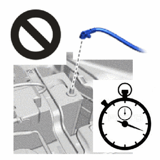
After turning the ignition switch off, waiting time may be required before disconnecting the cable from the negative (-) auxiliary battery terminal. Therefore, make sure to read the disconnecting the cable from the negative (-) auxiliary battery terminal notices before proceeding with work.
Click here
-
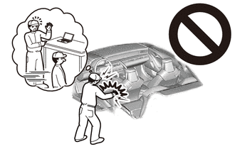
Do not remove the main body ECU (multiplex network body ECU) except when replacing it.
-
When removing the main body ECU (multiplex network body ECU), always replace it with a new one.
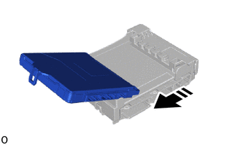
2. REMOVE DECK BOARD ASSEMBLY (for HV Model)
Click here
3. REMOVE REAR NO. 2 FLOOR BOARD (for HV Model)
Click here
4. REMOVE BATTERY HOLE COVER (for HV Model)
Click here
5. DISCONNECT CABLE FROM NEGATIVE AUXILIARY BATTERY TERMINAL
-
for A25A-FKS:
Click here
-
for A25A-FXS:
Click here
-
Wait at least 90 seconds after disconnecting the cable from the negative (-) auxiliary battery terminal to disable the SRS system.
-
If the airbag deploys for any reason, it may cause a serious accident.
NOTICE:
When disconnecting the cable, some systems need to be initialized after the cable is reconnected.
Click here
6. REMOVE LOWER NO. 1 INSTRUMENT PANEL AIRBAG ASSEMBLY
Click here
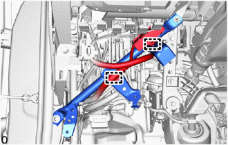
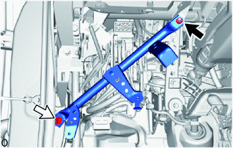
7. REMOVE NO. 3 INSTRUMENT PANEL TO COWL BRACE SUB-ASSEMBLY (for TMC Made)
|
(a) Detach the 2 wire harness clamps.
|
|
(b) Remove the nut, bolt and No. 3 instrument panel to cowl brace sub-assembly.

|
Nut
|

|
Bolt
|
8. REMOVE CENTER INSTRUMENT PANEL BRACKET SUB-ASSEMBLY (for TMMC Made)
HINT:
Use the same procedure described as for the No. 3 instrument panel to cowl brace sub-assembly (for TMC Made).
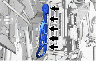
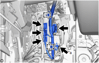
9. REMOVE INSTRUMENT PANEL JUNCTION BLOCK ASSEMBLY WITH MAIN BODY ECU
|
(a) Detach the 2 wire harness clamps.
|
|
|
*a
|
w/ Clearance Warning System
|
|
|
(b) w/ Clearance Warning System:
(1) Disconnect the 5 connectors.
(c) w/o Clearance Warning System:
(1) Disconnect the 4 connectors.
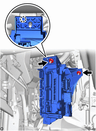
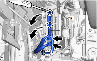
(d) Using a thin-bladed screwdriver with its tip wrapped with protective tape, detach the claw and disconnect the 2 lever connectors.
|
*a
|
Lever Connector
|

|
Rotate in this Direction
|

|
Protective Tape
|
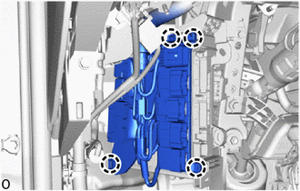
(e) Detach the wire harness clamp.
(f) Disconnect the 2 connectors.
|
(g) Disconnect the 5 connectors.
|
|
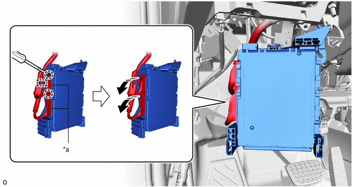
(i) Detach the claw and disconnect the instrument panel junction block assembly with main body ECU.
|
(j) Detach the claw and remove the instrument panel junction block assembly with main body ECU from the connector holder.
|
|
(k) Using a thin-bladed screwdriver with its tip wrapped with protective tape, detach the claw and disconnect the 2 lever connectors.
|
*a
|
Lever Connector
|
-
|
-
|
|
|
Rotate in this Direction
|
|
Protective Tape
|
(l) Detach the wire harness clamp and remove the instrument panel junction block assembly with main body ECU.
10. REMOVE MAIN BODY ECU (MULTIPLEX NETWORK BODY ECU)
|
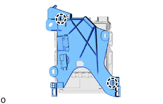
(a) Detach the claw and remove the junction block bracket from the instrument panel junction block assembly with main body ECU.
|
|
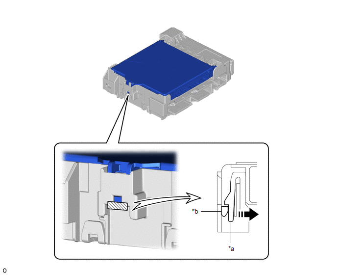
(b) Press the lock of the instrument panel junction block assembly and release the lock of the main body ECU (multiplex network body ECU) as shown in the illustration.
|
*a
|
Instrument Panel Junction Block Assembly
|
*b
|
Main Body ECU (Multiplex Network Body ECU)
|
|
|
Movement Direction
|
|
Instrument Panel Junction Block Assembly Lock
|
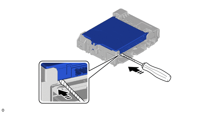
(c) While pressing the lock, horizontally insert a thin-bladed screwdriver with its tip wrapped with protective tape between the main body ECU (multiplex network body ECU) and instrument panel junction block assembly.
NOTICE:
Use a screwdriver with a diameter between 5.0 mm (0.197 in.) and 6.3 mm (0.248 in.) and a length of approximately 90 mm (3.54 in.).
|
|
Horizontally Insert a Thin-bladed Screwdriver
|
|
Protective Tape
|
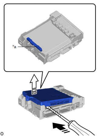
(d) When the thin-bladed screwdriver with its tip wrapped with protective tape is inserted, the internal connector lock is released.
|
*a
|
Internal Connector
|
|
|
Insert a Thin-bladed Screwdriver in this Direction
|

|
Released in this Direction
|
|
|
Protective Tape
|
NOTICE:
-
Do not twist the screwdriver to raise the main body ECU (multiplex network body ECU).
-
Do not excessively insert the screwdriver. Otherwise, the internal connector terminals may become deformed or damaged.
-
Replace the instrument panel junction block assembly when the connector terminal, the locking section, or the case is damaged or deformed.
|
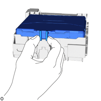
(e) Hold the rib of the main body ECU (multiplex network body ECU).
|
|
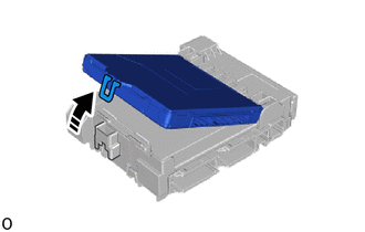
(f) While rotating the main body ECU (multiplex network body ECU), completely release the lock.
|
|
Rotate in this Direction
|
(g) Remove the main body ECU (multiplex network body ECU) from the instrument panel junction block assembly.
|
|
Remove in this Direction
|
|