- Ignition switch ON (do not start the engine and electric motor)
- Ambient temperature: 25°C (77°F)
| Last Modified: 01-30-2024 | 6.11:8.1.0 | Doc ID: RM10000000221JI |
| Model Year Start: 2022 | Model: RAV4 | Prod Date Range: [12/2021 - ] |
| Title: HEATING / AIR CONDITIONING: AIR CONDITIONING SYSTEM (for Gasoline Model): TERMINALS OF ECU; 2022 - 2024 MY RAV4 [12/2021 - ] | ||
TERMINALS OF ECU
|
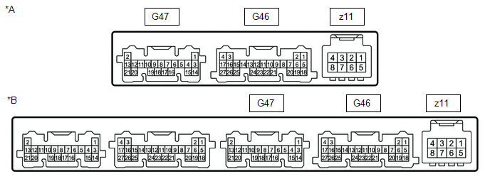
*A |
w/o Front Seat Heater System |
*B |
w/ Front Seat Heater System |
AIR CONDITIONING AMPLIFIER ASSEMBLY
(a) Disconnect the G46 air conditioning amplifier assembly connector.
(b) Measure the voltage and resistance according to the value(s) in the table below.
|
Terminal No. (Symbol) |
Wiring Color |
Terminal Description |
Condition |
Specified Condition |
|---|---|---|---|---|
|
G46-5 (B) - Body ground |
G - Body ground |
Power source (Back-up) |
Always |
11 to 14 V |
|
G46-6 (IG+) - Body ground |
GR - Body ground |
Power source (IG) |
Ignition switch ON |
11 to 14 V |
|
Ignition switch off |
Below 1 V |
|||
|
G46-17 (GND) - Body ground |
W-B - Body ground |
Ground |
Always |
Below 1 Ω |
(c) Reconnect the G46 air conditioning amplifier assembly connector.
(d) Measure the voltage, resistance and pulse according to the value(s) in the table below.
|
Terminal No. (Symbol) |
Wiring Color |
Terminal Description |
Condition |
Specified Condition |
|---|---|---|---|---|
|
G47-1 (TAM) - G47-14 (SG-2) |
R - R |
Ambient temperature sensor signal |
|
1.05 to 1.45 V |
|
0.64 to 0.87 V |
|||
|
G47-3 (SG-1) - Body ground* |
G - Body ground |
Ground for sensor |
Always |
Below 1 Ω |
|
G47-5 (TR) - Body ground* |
GR - Body ground |
Room temperature sensor signal |
|
1.05 to 1.45 V |
|
0.64 to 0.87 V |
|||
|
G47-6 (PRE) - G46-15 (SG-4) |
GR - L |
Air conditioner pressure sensor signal |
|
0.74 to 4.61 V |
|
Below 0.74 V |
|||
|
4.61 V or higher |
|||
|
G47-11 (S5-3) - Body ground |
L - Body ground |
Power source of sensor |
Ignition switch off → ON |
Below 1 V → 4.75 to 5.25 V |
|
G47-14 (SG-2) - Body ground |
R - Body ground |
Ground for sensor |
Always |
Below 1 Ω |
|
G47-15 (SG-4) - Body ground |
L - Body ground |
Ground for sensor |
Always |
Below 1 Ω |
|
G46-4 (CANL) |
- |
CAN communication line |
- |
- |
|
G46-5 (CANH) |
- |
CAN communication line |
- |
- |
|
G46-18 (SOL+) - Body ground |
R - Body ground |
Compressor solenoid operation signal |
|
Pulse generation (See waveform 4) |
|
G46-11 (ECOS) - Body ground |
W - Body ground |
Integration control and panel assembly (ECO switch) signal |
|
11 to 14 V → Below 1 V |
|
G46-7 (LIN1) - Body ground |
BE - Body ground |
LIN communication signal |
Ignition switch ON |
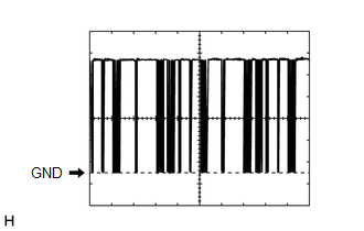
Pulse generation (See waveform 1) |
|
G46-21 (BLW) - Body ground |
Y - Body ground |
Blower motor speed control signal |
|
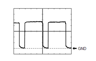
Pulse generation (See waveform 2) |
|
z11-2 (BUS G) - Body ground |
- |
Ground for BUS IC |
Always |
Below 1 Ω |
|
z11-3 (BUS) - z11-2 (BUS G) |
- |
BUS IC control signal |
Ignition switch ON |
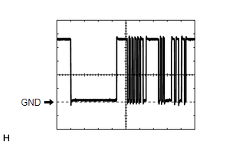
Pulse generation (See waveform 3) |
|
z11-4 (B BUS) - z11-2 (BUS G) |
- |
Power supply for BUS IC |
Ignition switch off |
11 to 14 V |
|
z11-5 (SGA) - Body ground |
- |
Ground for No. 1 cooler thermistor |
Always |
Below 1 Ω |
|
z11-6 (TEA) - z11-5 (SGA) |
- |
No. 1 cooler thermistor signal |
|
1.7 to 2.1 V |
|
0.9 to 1.3 V |
- *: for Automatic Air Conditioning System
(e) Waveform 1:
|
Item |
Content |
|---|---|
|
Terminal No. |
G46-7 (LIN1) - Body ground |
|
Tool Setting |
2 V/DIV., 20 μs./DIV. |
|
Vehicle Condition |
Ignition switch ON |
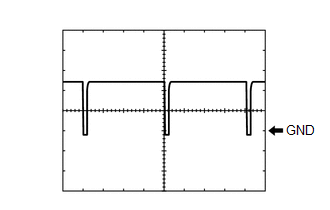
(f) Waveform 2:
|
Item |
Content |
|---|---|
|
Terminal No. |
G46-21 (BLW) - Body ground |
|
Tool Setting |
1 V/DIV., 500 μs./DIV. |
|
Vehicle Condition |
|
(g) Waveform 3:
|
Item |
Content |
|---|---|
|
Terminal No. |
z11-3 (BUS) - z11-2 (BUS G) |
|
Tool Setting |
2 V/DIV., 20 μs./DIV. |
|
Vehicle Condition |
Ignition switch ON |
(h) Waveform 4:
|
Item |
Content |
|---|---|
|
Terminal No. |
G46-18 (SOL+) - Body ground |
|
Tool Setting |
5 V/DIV., 500 μs./DIV. |
|
Condition |
|

AIR CONDITIONING CONTROL ASSEMBLY
(a) Disconnect the G24 air conditioning control assembly connector.
(b) Measure the voltage and resistance according to the value(s) in the table below.
|
Terminal No. (Symbol) |
Wiring Color |
Terminal Description |
Condition |
Specified Condition |
|---|---|---|---|---|
|
G24-13 (GND) - Body ground |
W-B - Body ground |
Ground |
Always |
Below 1 Ω |
|
G24-9 (IG+) - Body ground |
LA-B - Body ground |
Power source (IG) |
Ignition switch off |
Below 1 V |
|
Ignition switch ON |
10.5 to 16 V*1 11 to 14 V*2 |
- *1: w/ Stop and Start System
- *2: w/o Stop and Start System
(c) Reconnect the G24 integration control and panel assembly connector.
(d) Check for waveform according to the value(s) in the table below.
|
Terminal No. (Symbol) |
Wiring Color |
Terminal Description |
Condition |
Specified Condition |
|---|---|---|---|---|
|
G24-7 (LIN1) - Body ground |
LG - Body ground |
LIN communication |
Ignition switch ON |
Pulse generation (See waveform 1) |
(e) Waveform 1:
|
Item |
Content |
|---|---|
|
Terminal No. |
G24-7 (LIN1) - Body ground |
|
Tool Setting |
2 V/DIV., 20 μs./DIV. |
|
Vehicle Condition |
Ignition switch ON |
ECM
Click here
![2022 - 2024 MY RAV4 RAV4 HV [12/2021 - ]; A25A-FKS (ENGINE CONTROL): SFI SYSTEM: TERMINALS OF ECM](/t3Portal/stylegraphics/info.gif)
MAIN BODY ECU (MULTIPLEX NETWORK BODY ECU)
Click here
|
|
|