| Last Modified: 01-30-2024 | 6.11:8.1.0 | Doc ID: RM1000000021N6P |
| Model Year Start: 2022 | Model: RAV4 | Prod Date Range: [12/2021 - ] |
| Title: A25A-FKS (ENGINE CONTROL): SFI SYSTEM: Drive Start Control; 2022 - 2024 MY RAV4 RAV4 HV [12/2021 - ] | ||
|
Drive Start Control |
DESCRIPTION
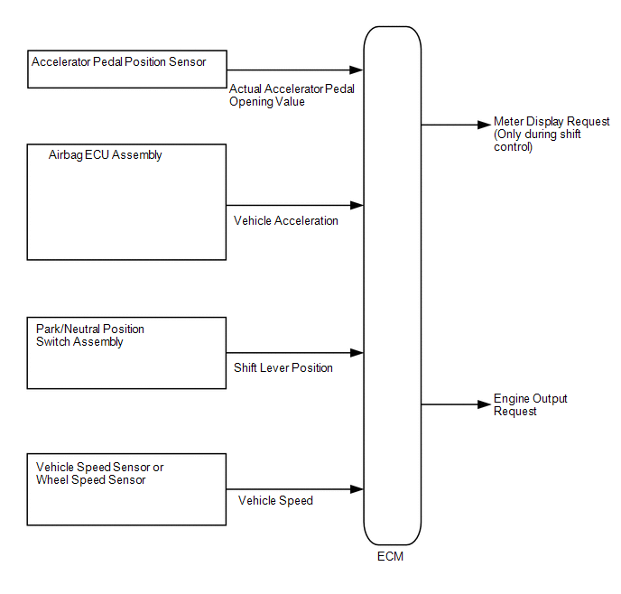
The drive start control is controlled by the ECM.
If the ECM determines that the shift lever and accelerator pedal are operated abnormally, engine output is restricted and, when necessary, a warning is displayed on the combination meter assembly.
CAUTION / NOTICE / HINT
HINT:
Even if the accelerator pedal position is maintained, the engine output may increase when driving uphill and decrease when driving downhill. This is due to the drive start control controlling the engine output, and is not a malfunction.
PROCEDURE
|
1. |
SYMPTOM CONFIRMATION |
(a) Interview the customer to confirm the problem.
|
Result |
Proceed to |
|---|---|
|
Hunting |
A |
|
Hesitation/poor acceleration |
B |
| B |

|
|

|
2. |
PAST ACTIVATION CONFIRMATION |
(a) Check if the customer operated the vehicle in a way that would cause the drive start control to operate.
Drive Start Control Activation Conditions
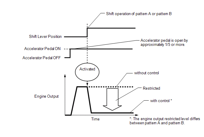
Shift control
- Activation conditions
-
Pattern A (When all of the following conditions are met, control starts.)
- The accelerator pedal is open by approximately 1/5 or more.
- The shift lever is moved from P to any forward position (D or S) or R.
-
Pattern B (When all of the following conditions are met, control starts.)
- The accelerator pedal is open by approximately 1/5 or more.
-
The shift lever is moved from R to any forward position (D or S), any forward position (D or S) to R, or N to R.

-
Items Controlled
- Engine output is restricted.
-
Deactivation Conditions
- The accelerator pedal is released.
- The shift lever is in P or N.
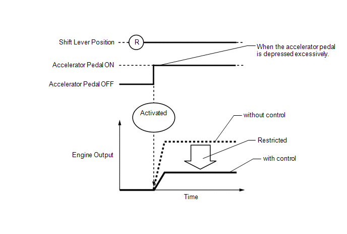
Reverse control
- Activation conditions
- The shift lever is in R.
-
The accelerator pedal is depressed excessively.
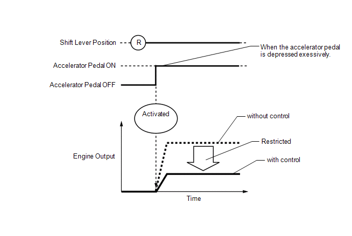
-
Items Controlled
- Engine output is restricted.
-
Deactivation Conditions
- The accelerator pedal is released.
- The shift lever is moved to any position other than R.
HINT:
- The engine output restricted level differs between pattern A, pattern B and Reverse control.
- During reverse control or shift control, engine output is adjusted based on the road gradient.
|
Result |
Proceed to |
|---|---|
|
Performed |
A |
|
Not performed |
B |
| B |
|
|
|
3. |
CHECK DTC OUTPUT |
(a) Connect the Techstream to the DLC3.
(b) Turn the ignition switch to ON.
(c) Turn the Techstream on.
(d) Enter the following menus: System Select / Health Check.
(e) Check the DTCs.
|
Result |
Proceed to |
|---|---|
|
DTCs are not output |
A |
|
DTCs are output |
B |
| B |
|
GO TO DTC CHART |
|
|
4. |
READ VALUE USING TECHSTREAM (FR, FL, RR, RL WHEEL SPEED) |
(a) Connect the Techstream to the DLC3.
(b) Turn the ignition switch to ON.
(c) Turn the Techstream on.
(d) Start the engine.
(e) Enter the following menus: Chassis / Brake/EPB / Data List / FR Wheel Speed, FL Wheel Speed, RR Wheel Speed and RL Wheel Speed.
Chassis > Brake/EPB > Data List
|
Tester Display |
|---|
|
FR Wheel Speed |
|
FL Wheel Speed |
|
RR Wheel Speed |
|
RL Wheel Speed |
(f) Read the value displayed on the Techstream.
Standard:
|
Techstream Display |
Condition |
Specified Condition |
|---|---|---|
|
FR Wheel Speed FL Wheel Speed RR Wheel Speed RL Wheel Speed |
Vehicle stopped, engine running |
0 km/h (0 mph) |
|
Vehicle being driven at constant speed between 16.1 to 64.4 km/h (10 to 40 mph) |
No large fluctuations when driving at a constant speed |
CAUTION:
When performing a drive test, obey all speed limits and traffic laws.
HINT:
Data can be captured relatively easily by using the snapshot function in the Data List. Confirm the data after performing the drive test.
| NG |
|
INSPECT FRONT OR REAR SPEED SENSOR |
|
|
5. |
READ VALUE USING TECHSTREAM (FORWARD AND REARWARD G) |
(a) Connect the Techstream to the DLC3.
(b) Start the engine.
(c) Turn the Techstream on.
(d) Enter the following menus: Chassis / Brake/EPB / Data List / Forward and Rearward G.
Chassis > Brake/EPB > Data List
|
Tester Display |
|---|
|
Forward and Rearward G |
(e) Read the value displayed on the Techstream.
Standard:
|
Techstream Display |
Condition |
Specified Condition |
|---|---|---|
|
Forward and Rearward G |
During deceleration |
Value changes with vehicle speed |
|
During acceleration |
Value changes with vehicle speed |
CAUTION:
When performing a drive test, obey all speed limits and traffic laws.
HINT:
Data can be captured relatively easily by using the snapshot function in the Data List. Confirm the data after performing the drive test.
| OK |
|
| NG |
|
|
6. |
PAST ACTIVATION CONFIRMATION |
(a) Check if the customer operated the vehicle in a way that would cause the drive start control to operate.
Drive Start Control Activation Conditions
Shift control
- Activation conditions
-
Pattern A (When all of the following conditions are met, control starts.)
- The accelerator pedal is open by approximately 1/5 or more.
- The shift lever is moved from P to any forward position (D or S) or R.
-
Pattern B (When all of the following conditions are met, control starts.)
- The accelerator pedal is open by approximately 1/5 or more.
-
The shift lever is moved from R to any forward position (D or S), any forward position (D or S) to R, or N to R.
-
Items Controlled
- Engine output is restricted.
-
Deactivation Conditions
- The accelerator pedal is released.
- The shift lever is in P or N.
Reverse control
- Activation conditions
- The shift lever is in R.
-
The accelerator pedal is depressed excessively.
-
Items Controlled
- Engine output is restricted.
-
Deactivation Conditions
- The accelerator pedal is released.
- The shift lever is moved to any position other than R.
HINT:
- The engine output restricted level differs between pattern A, pattern B and Reverse control.
- During reverse control or shift control, engine output is adjusted based on the road gradient.
|
Result |
Proceed to |
|---|---|
|
Performed |
A |
|
Not performed |
B |
| A |
|
SYSTEM NORMAL |
|
|
7. |
CHECK DTC OUTPUT |
(a) Connect the Techstream to the DLC3.
(b) Turn the ignition switch to ON.
(c) Turn the Techstream on.
(d) Enter the following menus: System Select / Health Check.
(e) Check the DTCs.
|
Result |
Proceed to |
|---|---|
|
DTCs are not output |
A |
|
DTCs are output |
B |
| B |
|
GO TO DTC CHART |
|
|
8. |
INSPECT PARK/NEUTRAL POSITION SWITCH ASSEMBLY |
(a) Inspect the park/neutral position switch assembly.
-
for 2WD:
Click here
![2019 - 2024 MY RAV4 [11/2018 - ]; UB80E (AUTOMATIC TRANSMISSION / TRANSAXLE): PARK / NEUTRAL POSITION SWITCH: INSPECTION](/t3Portal/stylegraphics/info.gif)
-
for AWD:
Click here
|
Result |
Proceed to |
|---|---|
|
Normal |
A |
|
Abnormal |
B |
| B |
|
REPLACE PARK/NEUTRAL POSITION SWITCH ASSEMBLY
|
|
|
9. |
READ VALUE USING TECHSTREAM (ACCELERATOR POSITION SENSOR NO. 1 VOLTAGE % AND NO. 2 VOLTAGE %) |
(a) Connect the Techstream to the DLC3.
(b) Turn the ignition switch to ON.
(c) Turn the Techstream on.
(d) Enter the following menus: Powertrain / Engine / Data List / Accelerator Position Sensor No.1 Voltage % and Accelerator Position Sensor No.2 Voltage %.
Powertrain > Engine > Data List
|
Tester Display |
|---|
|
Accelerator Position Sensor No.1 Voltage % |
|
Accelerator Position Sensor No.2 Voltage % |
(e) Read the value displayed on the Techstream.
OK:
|
Techstream Display |
Condition |
Specified Condition |
|---|---|---|
|
Accelerator Position Sensor No.1 Voltage % |
Accelerator Pedal Released → Depressed |
Values smoothly change following accelerator pedal operation |
|
Accelerator Position Sensor No.2 Voltage % |
HINT:
For numerical values of Accelerator Position Sensor No.1 Voltage % and Accelerator Position Sensor No.2 Voltage %, refer to the Data List.
Click here
| OK |
|
| NG |
|
|
|
|