
- Short to ground
- +B short
| Last Modified: 01-30-2024 | 6.11:8.1.0 | Doc ID: RM1000000021JPW |
| Model Year Start: 2022 | Model: RAV4 HV | Prod Date Range: [12/2021 - ] |
| Title: PARK ASSIST / MONITORING: PARKING SUPPORT BRAKE SYSTEM (for HV Model): U117787,U117887; Lost Communication with Side Obstacle Detection Control Module "A" (ch2) Missing Message; 2022 - 2024 MY RAV4 HV [12/2021 - ] | ||
|
DTC |
U117787 |
Lost Communication with Side Obstacle Detection Control Module "A" (ch2) Missing Message |
|
DTC |
U117887 |
Lost Communication with Side Obstacle Detection Control Module "B" (ch2) Missing Message |
DESCRIPTION
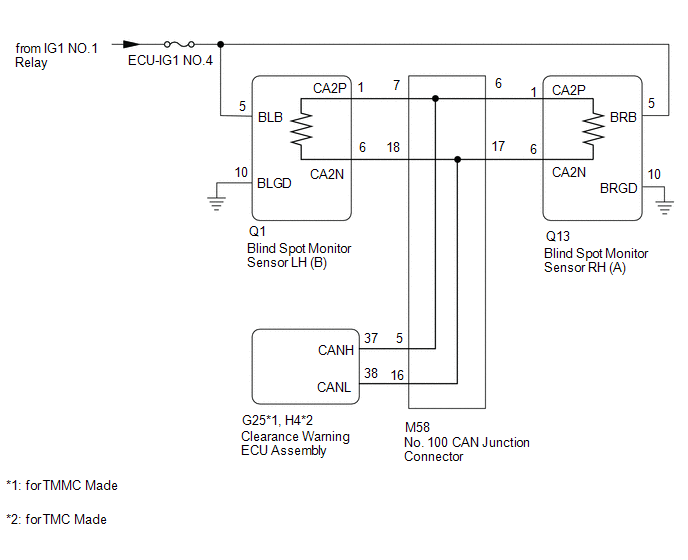
This DTC is output when the clearance warning ECU assembly detects lost communication with the blind spot monitor sensor.
|
DTC No. |
Detection Item |
DTC Detection Condition |
Trouble Area |
|---|---|---|---|
|
U117787 |
Lost Communication with Side Obstacle Detection Control Module "A" (ch2) Missing Message |
The clearance warning ECU assembly is unable to receive communication from the blind spot monitor sensor RH (A) |
|
|
U117887 |
Lost Communication with Side Obstacle Detection Control Module "B" (ch2) Missing Message |
The clearance warning ECU assembly is unable to receive communication from the blind spot monitor sensor LH (B) |
|
WIRING DIAGRAM
CAUTION / NOTICE / HINT
NOTICE:
- Inspect the fuses for circuits related to this system before performing the following procedure.
- Before measuring the resistance of the CAN bus, turn the power switch off and leave the vehicle for 1 minute or more without operating the key or any switches, or opening or closing the doors. After that, disconnect the cable from the negative (-) auxiliary battery terminal and leave the vehicle for 1 minute or more before measuring the resistance.
-
After turning the power switch off, waiting time may be required before disconnecting the cable from the negative (-) auxiliary battery terminal. Therefore, make sure to read the disconnecting the cable from the negative (-) auxiliary battery terminal notices before proceeding with work.
Click here
![2019 - 2024 MY RAV4 RAV4 HV [11/2018 - ]; INTRODUCTION: REPAIR INSTRUCTION: PRECAUTION](/t3Portal/stylegraphics/info.gif)
HINT:
- Operating the power switch, any other switches or a door triggers related ECU and sensor communication on the CAN. This communication will cause the resistance value to change.
- Even after DTCs are cleared, if a DTC is stored again after driving the vehicle for a while, the malfunction may be occurring due to vibration of the vehicle. In such a case, wiggling the ECUs or wire harness while performing the inspection below may help determine the cause of the malfunction.
PROCEDURE
|
1. |
CHECK FOR DTC |
(a) Check for DTCs.
Click here
Body Electrical > Clearance Warning > Trouble Codes
(b) Clear the DTCs.
Click here
Body Electrical > Clearance Warning > Clear DTCs
(c) Recheck for DTCs.
Click here
Body Electrical > Clearance Warning > Trouble Codes
|
Result |
Proceed to |
|---|---|
|
DTC U117787 only is output |
A |
|
DTC U117887 only is output |
B |
|
DTC U117787 and U117887 are output |
C |
| B |

|
| C |
|
|
|
2. |
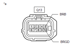
CHECK HARNESS AND CONNECTOR (BLIND SPOT MONITOR SENSOR RH (A) - BATTERY AND BODY GROUND) |
|
(a) Disconnect the blind spot monitor sensor RH (A) connector. |
|
(b) Measure the resistance according to the value(s) in the table below.
Standard Resistance:
|
Tester Connection |
Condition |
Specified Condition |
|---|---|---|
|
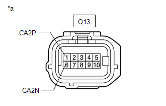
Q13-10 (BRGD) - Body ground |
Always |
Below 1 Ω |
(c) Measure the voltage according to the value(s) in the table below.
Standard Voltage:
|
Tester Connection |
Switch Condition |
Specified Condition |
|---|---|---|
|
Q13-5 (BRB) - Body ground |
Power switch on (IG) |
11 to 14 V |
|
Q13-5 (BRB) - Body ground |
Power switch off |
Below 1 V |
| OK |
|
REPLACE BLIND SPOT MONITOR SENSOR RH (A)
|
| NG |
|
REPAIR OR REPLACE HARNESS OR CONNECTOR |
|
3. |
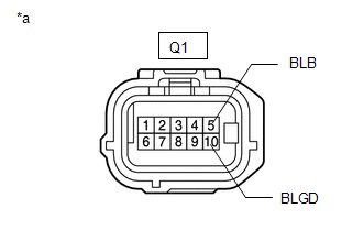
CHECK HARNESS AND CONNECTOR (BLIND SPOT MONITOR SENSOR LH (B) - BATTERY AND BODY GROUND) |
|
(a) Disconnect the blind spot monitor sensor LH (B) connector. |
|
(b) Measure the resistance according to the value(s) in the table below.
Standard Resistance:
|
Tester Connection |
Condition |
Specified Condition |
|---|---|---|
|
Q1-10 (BLGD) - Body ground |
Always |
Below 1 Ω |
(c) Measure the voltage according to the value(s) in the table below.
Standard Voltage:
|
Tester Connection |
Switch Condition |
Specified Condition |
|---|---|---|
|
Q1-5 (BLB) - Body ground |
Power switch on (IG) |
11 to 14 V |
|
Q1-5 (BLB) - Body ground |
Power switch off |
Below 1 V |
| OK |
|
REPLACE BLIND SPOT MONITOR SENSOR LH (B)
|
| NG |
|
REPAIR OR REPLACE HARNESS OR CONNECTOR |
|
4. |
CHECK CAN BUS MAIN WIRE |
|
(a) Turn the power switch off. |
|
(b) Disconnect the cable from the negative (-) auxiliary battery terminal.
(c) Measure the resistance according to the value(s) in the table below.
Standard Resistance:
|
Tester Connection |
Condition |
Specified Condition |
Result |
|---|---|---|---|
|
M58-5 (CANH) - M58-16 (CANL) |
Cable disconnected from negative (-) auxiliary battery terminal |
54 to 69 Ω |
Below 54 Ω: Short circuit between bus lines |
|
70 Ω or more: Open circuit in main bus lines |
|||
|
M58-5 (CANH) - G114-4 (CG) |
Cable disconnected from negative (-) auxiliary battery terminal |
200 Ω or higher |
Below 200 Ω: CANH short to ground |
|
M58-16 (CANL) - G114-4 (CG) |
Cable disconnected from negative (-) auxiliary battery terminal |
200 Ω or higher |
Below 200 Ω: CANL short to ground |
|
M58-5 (CANH) - G114-16 (BAT) |
Cable disconnected from negative (-) auxiliary battery terminal |
6 kΩ or higher |
Below 6 kΩ: CANH +B short |
|
M58-16 (CANL) - G114-16 (BAT) |
Cable disconnected from negative (-) auxiliary battery terminal |
6 kΩ or higher |
Below 6 kΩ: CANL +B short |
|
Result |
Proceed to |
|---|---|
|
OK |
A |
|
Open circuit in CAN main bus lines |
B |
|
Short circuit between bus lines |
C |
|
|
D |
| B |
|
| C |
|
| D |
|
|
|
5. |
CHECK FOR DTC |
(a) Reconnect the cable to the negative (-) auxiliary battery terminal.
NOTICE:
When disconnecting the cable, some systems need to be initialized after the cable is reconnected.
Click here
(b) Clear the DTCs.
Click here
Body Electrical > Clearance Warning > Clear DTCs
(c) Check for DTCs.
Click here
Body Electrical > Clearance Warning > Trouble Codes
|
Result |
Proceed to |
|---|---|
|
DTC U117787 and U117887 are not output |
A |
|
DTC U117787 and U117887 are output |
B |
| A |
|
| B |
|
|
6. |
CHECK FOR OPEN IN CAN BUS WIRE (NO. 100 JUNCTION CONNECTOR) |
(a) Disconnect the No. 100 CAN junction connector.
|
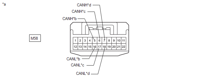
*a |
Front view of wire harness connector (to No. 100 CAN Junction Connector) |
*b |
to Clearance Warning ECU Assembly CAN Wire |
|
*c |
to Blind Spot Monitor Sensor RH (A) CAN Main Wire |
*d |
to Blind Spot Monitor Sensor LH (B) CAN Main Wire |
(b) Measure the resistance according to the value(s) in the table below.
Standard Resistance:
|
Tester Connection |
Condition |
Specified Condition |
|---|---|---|
|
M58-5 (CANH) - M58-16 (CANL) |
Cable disconnected from negative (-) auxiliary battery terminal |
200 Ω or higher |
|
M58-6 (CANH) - M58-17 (CANL) |
Cable disconnected from negative (-) auxiliary battery terminal |
108 to 132 Ω |
|
M58-7 (CANH) - M58-18 (CANL) |
Cable disconnected from negative (-) auxiliary battery terminal |
108 to 132 Ω |
|
Result |
Proceed to |
|---|---|
|
OK |
A |
|
NG (to blind spot monitor sensor LH (B) CAN main wire) |
B |
|
NG (to blind spot monitor sensor RH (A) CAN main wire) |
C |
|
NG (to clearance warning ECU assembly CAN wire) |
D |
| A |
|
REPLACE NO. 100 CAN JUNCTION CONNECTOR |
| C |
|
| D |
|
|
|
7. |
CHECK FOR OPEN IN CAN BUS MAIN WIRE (BLIND SPOT MONITOR SENSOR LH (B)) |
|
(a) Reconnect the M58 No. 100 CAN junction connector. |
|

(b) Disconnect the blind spot monitor sensor LH (B) connector.
(c) Measure the resistance according to the value(s) in the table below.
Standard Resistance:
|
Tester Connection |
Condition |
Specified Condition |
|---|---|---|
|
Q1-1 (CA2P) - Q1-6 (CA2N) |
Cable disconnected from negative (-) auxiliary battery terminal |
108 to 132 Ω |
| OK |
|
REPLACE BLIND SPOT MONITOR SENSOR LH (B)
|
| NG |
|
REPAIR OR REPLACE CAN MAIN WIRE OR CONNECTOR (BLIND SPOT MONITOR SENSOR LH (B) - NO. 100 CAN JUNCTION CONNECTOR) |
|
8. |
CHECK FOR OPEN IN CAN BUS MAIN WIRE (BLIND SPOT MONITOR SENSOR RH (A)) |
|
(a) Reconnect the M58 No. 100 CAN junction connector. |
|
(b) Disconnect the blind spot monitor sensor RH (A) connector.
(c) Measure the resistance according to the value(s) in the table below.
Standard Resistance:
|
Tester Connection |
Condition |
Specified Condition |
|---|---|---|
|
Q13-1 (CA2P) - Q13-6 (CA2N) |
Cable disconnected from negative (-) auxiliary battery terminal |
108 to 132 Ω |
| OK |
|
REPLACE BLIND SPOT MONITOR SENSOR RH (A)
|
| NG |
|
REPAIR OR REPLACE CAN MAIN WIRE OR CONNECTOR (BLIND SPOT MONITOR SENSOR RH (A) - NO. 100 CAN JUNCTION CONNECTOR) |
|
9. |
CHECK FOR OPEN IN CAN BUS WIRE (CLEARANCE WARNING ECU ASSEMBLY) |
|
(a) Reconnect the M58 No. 100 CAN junction connector. |
|
(b) Disconnect the clearance warning ECU connector.
(c) Measure the resistance according to the value(s) in the table below.
Standard Resistance:
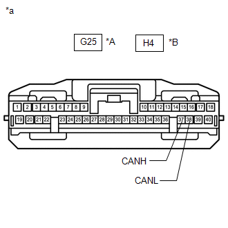
for TMMC Made:
|
Tester Connection |
Condition |
Specified Condition |
|---|---|---|
|
G25-37 (CANH) - G25-38 (CANL) |
Cable disconnected from negative (-) auxiliary battery terminal |
54 to 69 Ω |
for TMC Made:
|
Tester Connection |
Condition |
Specified Condition |
|---|---|---|
|
H4-37 (CANH) - H4-38 (CANL) |
Cable disconnected from negative (-) auxiliary battery terminal |
54 to 69 Ω |
| OK |
|
| NG |
|
REPAIR OR REPLACE CAN BUS WIRE (CLEARANCE WARNING ECU ASSEMBLY - NO. 100 CAN JUNCTION CONNECTOR) |
|
10. |
CHECK FOR SHORT IN CAN BUS WIRES (NO. 100 JUNCTION CONNECTOR) |
(a) Disconnect the No. 100 CAN junction connector.
|
*a |
Front view of wire harness connector (to No. 100 CAN Junction Connector) |
*b |
to Clearance Warning ECU Assembly CAN Wire |
|
*c |
to Blind Spot Monitor Sensor RH (A) CAN Main Wire |
*d |
to Blind Spot Monitor Sensor LH (B) CAN Main Wire |
(b) Measure the resistance according to the value(s) in the table below.
Standard Resistance:
|
Tester Connection |
Condition |
Specified Condition |
|---|---|---|
|
M58-5 (CANH) - M58-16 (CANL) |
Cable disconnected from negative (-) auxiliary battery terminal |
200 Ω or higher |
|
M58-6 (CANH) - M58-17 (CANL) |
Cable disconnected from negative (-) auxiliary battery terminal |
108 to 132 Ω |
|
M58-7 (CANH) - M58-18 (CANL) |
Cable disconnected from negative (-) auxiliary battery terminal |
108 to 132 Ω |
|
Result |
Proceed to |
|---|---|
|
OK |
A |
|
NG (to blind spot monitor sensor LH (B) CAN main wire) |
B |
|
NG (to blind spot monitor sensor RH (A) CAN main wire) |
C |
|
NG (to clearance warning ECU assembly CAN wire) |
D |
| A |
|
REPLACE NO. 100 CAN JUNCTION CONNECTOR |
| C |
|
| D |
|
|
|
11. |
CHECK FOR SHORT IN CAN BUS WIRES (BLIND SPOT MONITOR SENSOR LH (B)) |
|
(a) Reconnect the M58 No. 100 CAN junction connector. |
|
(b) Disconnect the blind spot monitor sensor LH (B) connector.
(c) Measure the resistance according to the value(s) in the table below.
Standard Resistance:
|
Tester Connection |
Condition |
Specified Condition |
|---|---|---|
|
Q1-1 (CA2P) - Q1-6 (CA2N) |
Cable disconnected from negative (-) auxiliary battery terminal |
108 to 132 Ω |
| OK |
|
REPLACE BLIND SPOT MONITOR SENSOR LH (B)
|
| NG |
|
REPAIR OR REPLACE CAN MAIN WIRE OR CONNECTOR (BLIND SPOT MONITOR SENSOR LH (B) - NO. 100 CAN JUNCTION CONNECTOR) |
|
12. |
CHECK FOR SHORT IN CAN BUS WIRES (BLIND SPOT MONITOR SENSOR RH (A)) |
|
(a) Reconnect the M58 No. 100 CAN junction connector. |
|
(b) Disconnect the blind spot monitor sensor RH (A) connector.
(c) Measure the resistance according to the value(s) in the table below.
Standard Resistance:
|
Tester Connection |
Condition |
Specified Condition |
|---|---|---|
|
Q13-1 (CA2P) - Q13-6 (CA2N) |
Cable disconnected from negative (-) auxiliary battery terminal |
108 to 132 Ω |
| OK |
|
REPLACE BLIND SPOT MONITOR SENSOR RH (A)
|
| NG |
|
REPAIR OR REPLACE CAN MAIN WIRE OR CONNECTOR (BLIND SPOT MONITOR SENSOR RH (A) - NO. 100 CAN JUNCTION CONNECTOR) |
|
13. |
CHECK FOR SHORT IN CAN BUS WIRES (CLEARANCE WARNING ECU ASSEMBLY) |
|
(a) Reconnect the M58 No. 100 CAN junction connector. |
|
(b) Disconnect the clearance warning ECU connector.
(c) Measure the resistance according to the value(s) in the table below.
Standard Resistance:
for TMMC Made:
|
Tester Connection |
Condition |
Specified Condition |
|---|---|---|
|
G25-37 (CANH) - G25-38 (CANL) |
Cable disconnected from negative (-) auxiliary battery terminal |
54 to 69 Ω |
for TMC Made:
|
Tester Connection |
Condition |
Specified Condition |
|---|---|---|
|
H4-37 (CANH) - H4-38 (CANL) |
Cable disconnected from negative (-) auxiliary battery terminal |
54 to 69 Ω |
| OK |
|
| NG |
|
REPAIR OR REPLACE CAN BUS WIRE (CLEARANCE WARNING ECU ASSEMBLY - NO. 100 CAN JUNCTION CONNECTOR) |
|
14. |
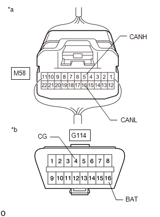
CHECK FOR SHORT IN CAN BUS WIRES (NO. 100 CAN JUNCTION CONNECTOR) |
(a) Disconnect the No. 100 CAN junction connector.
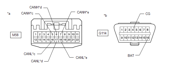
|
*a |
Front view of wire harness connector (to No. 100 CAN Junction Connector) |
*b |
Front view of DLC3 |
|
*c |
to Clearance Warning ECU Assembly CAN Wire |
*d |
to Blind Spot Monitor Sensor RH (A) CAN Main Wire |
|
*e |
to Blind Spot Monitor Sensor LH (B) CAN Main Wire |
- |
- |
(b) Measure the resistance according to the value(s) in the table below.
Standard Resistance:
|
Tester Connection |
Condition |
Specified Condition |
|---|---|---|
|
M58-5 (CANH) - G114-4 (CG) |
Cable disconnected from negative (-) auxiliary battery terminal |
200 Ω or higher |
|
M58-16 (CANL) - G114-4 (CG) |
Cable disconnected from negative (-) auxiliary battery terminal |
200 Ω or higher |
|
M58-5 (CANH) - G114-16 (BAT) |
Cable disconnected from negative (-) auxiliary battery terminal |
6 kΩ or higher |
|
M58-16 (CANL) - G114-16 (BAT) |
Cable disconnected from negative (-) auxiliary battery terminal |
6 kΩ or higher |
|
M58-6 (CANH) - G114-4 (CG) |
Cable disconnected from negative (-) auxiliary battery terminal |
200 Ω or higher |
|
M58-17 (CANL) - G114-4 (CG) |
Cable disconnected from negative (-) auxiliary battery terminal |
200 Ω or higher |
|
M58-6 (CANH) - G114-16 (BAT) |
Cable disconnected from negative (-) auxiliary battery terminal |
6 kΩ or higher |
|
M58-17 (CANL) - G114-16 (BAT) |
Cable disconnected from negative (-) auxiliary battery terminal |
6 kΩ or higher |
|
M58-7 (CANH) - G114-4 (CG) |
Cable disconnected from negative (-) auxiliary battery terminal |
200 Ω or higher |
|
M58-18 (CANL) - G114-4 (CG) |
Cable disconnected from negative (-) auxiliary battery terminal |
200 Ω or higher |
|
M58-7 (CANH) - G114-16 (BAT) |
Cable disconnected from negative (-) auxiliary battery terminal |
6 kΩ or higher |
|
M58-18 (CANL) - G114-16 (BAT) |
Cable disconnected from negative (-) auxiliary battery terminal |
6 kΩ or higher |
HINT:
Check for short that was confirmed to be a malfunction by confirming symptoms.
|
Result |
Proceed to |
|---|---|
|
OK |
A |
|
NG (to blind spot monitor sensor LH (B) CAN main wire) |
B |
|
NG (to blind spot monitor sensor RH (A) CAN main wire) |
C |
|
NG (to clearance warning ECU assembly CAN wire) |
D |
| A |
|
REPLACE NO. 100 CAN JUNCTION CONNECTOR |
| C |
|
| D |
|
|
|
15. |
CHECK FOR SHORT IN CAN BUS WIRES (BLIND SPOT MONITOR SENSOR LH (B)) |
|
(a) Reconnect the M58 No. 100 CAN junction connector. |
|
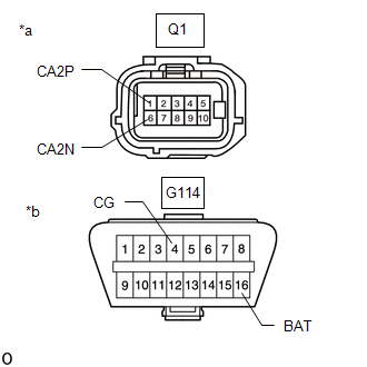
(b) Disconnect the blind spot monitor sensor LH (B) connector.
(c) Measure the resistance according to the value(s) in the table below.
Standard Resistance:
|
Tester Connection |
Condition |
Specified Condition |
|---|---|---|
|
Q1-1 (CA2P) - G114-4 (CG) |
Cable disconnected from negative (-) auxiliary battery terminal |
200 Ω or higher |
|
Q1-6 (CA2N) - G114-4 (CG) |
Cable disconnected from negative (-) auxiliary battery terminal |
200 Ω or higher |
|
Q1-1 (CA2P) - G114-16 (BAT) |
Cable disconnected from negative (-) auxiliary battery terminal |
6 kΩ or higher |
|
Q1-6 (CA2N) - G114-16 (BAT) |
Cable disconnected from negative (-) auxiliary battery terminal |
6 kΩ or higher |
| OK |
|
REPLACE BLIND SPOT MONITOR SENSOR LH (B)
|
| NG |
|
REPAIR OR REPLACE CAN MAIN WIRE OR CONNECTOR (BLIND SPOT MONITOR SENSOR LH (B) - NO. 100 CAN JUNCTION CONNECTOR) |
|
16. |
CHECK FOR SHORT IN CAN BUS WIRES (BLIND SPOT MONITOR SENSOR RH (A)) |
|
(a) Reconnect the M58 No. 100 CAN junction connector. |
|
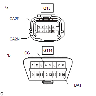
(b) Disconnect the blind spot monitor sensor RH (A) connector.
(c) Measure the resistance according to the value(s) in the table below.
Standard Resistance:
|
Tester Connection |
Condition |
Specified Condition |
|---|---|---|
|
Q13-1 (CA2P) - G114-4 (CG) |
Cable disconnected from negative (-) auxiliary battery terminal |
200 Ω or higher |
|
Q13-6 (CA2N) - G114-4 (CG) |
Cable disconnected from negative (-) auxiliary battery terminal |
200 Ω or higher |
|
Q13-1 (CA2P) - G114-16 (BAT) |
Cable disconnected from negative (-) auxiliary battery terminal |
6 kΩ or higher |
|
Q13-6 (CA2N) - G114-16 (BAT) |
Cable disconnected from negative (-) auxiliary battery terminal |
6 kΩ or higher |
| OK |
|
REPLACE BLIND SPOT MONITOR SENSOR RH (A)
|
| NG |
|
REPAIR OR REPLACE CAN MAIN WIRE OR CONNECTOR (BLIND SPOT MONITOR SENSOR RH (A) - NO. 100 CAN JUNCTION CONNECTOR) |
|
17. |
CHECK FOR SHORT IN CAN BUS WIRES (CLEARANCE WARNING ECU ASSEMBLY) |
|
(a) Reconnect the M58 No. 100 CAN junction connector. |
|
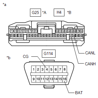
(b) Disconnect the clearance warning ECU connector.
(c) Measure the resistance according to the value(s) in the table below.
Standard Resistance:
for TMMC Made:
|
Tester Connection |
Condition |
Specified Condition |
|---|---|---|
|
G25-37 (CANH) - G114-4 (CG) |
Cable disconnected from negative (-) auxiliary battery terminal |
200 Ω or higher |
|
G25-38 (CANL) - G114-4 (CG) |
Cable disconnected from negative (-) auxiliary battery terminal |
200 Ω or higher |
|
G25-37 (CANH) - G114-16 (BAT) |
Cable disconnected from negative (-) auxiliary battery terminal |
6 kΩ or higher |
|
G25-38 (CANL) - G114-16 (BAT) |
Cable disconnected from negative (-) auxiliary battery terminal |
6 kΩ or higher |
for TMC Made:
|
Tester Connection |
Condition |
Specified Condition |
|---|---|---|
|
H4-37 (CANH) - G114-4 (CG) |
Cable disconnected from negative (-) auxiliary battery terminal |
200 Ω or higher |
|
H4-38 (CANL) - G114-4 (CG) |
Cable disconnected from negative (-) auxiliary battery terminal |
200 Ω or higher |
|
H4-37 (CANH) - G114-16 (BAT) |
Cable disconnected from negative (-) auxiliary battery terminal |
6 kΩ or higher |
|
H4-38 (CANL) - G114-16 (BAT) |
Cable disconnected from negative (-) auxiliary battery terminal |
6 kΩ or higher |
| OK |
|
| NG |
|
REPAIR OR REPLACE CAN BUS WIRE (CLEARANCE WARNING ECU ASSEMBLY - NO. 100 CAN JUNCTION CONNECTOR) |
|
|
|