| Last Modified: 01-30-2024 | 6.11:8.1.0 | Doc ID: RM1000000021J4V |
| Model Year Start: 2022 | Model: RAV4 | Prod Date Range: [12/2021 - 10/2022] |
| Title: BRAKE SYSTEM (OTHER): BRAKE BOOSTER PUMP (w/o Vacuum Brake Booster): REMOVAL; 2022 MY RAV4 RAV4 HV [12/2021 - 10/2022] | ||
REMOVAL
CAUTION / NOTICE / HINT
The necessary procedures (adjustment, calibration, initialization, or registration) that must be performed after parts are removed, installed, or replaced during brake booster pump assembly removal/installation are shown below.
Necessary Procedure After Parts Removed/Installed/Replaced (for HV Model)
|
Replaced Part or Performed Procedure |
Necessary procedures |
Effect/Inoperative Function when Necessary Procedure not Performed |
Link |
|---|---|---|---|
|
*: When performing learning using the Techstream.
Click here
|
|||
|
Disconnect cable from negative (-) auxiliary battery terminal |
Perform steering sensor zero point calibration |
Lane control system |
|
|
Parking support brake system (for HV model)* |
|||
|
Pre-collision system |
|||
|
Memorize steering angle neutral point |
Parking assist monitor system |
|
|
|
Panoramic view monitor system (for HV model) |
|
||
|
Reset back door close position |
Power back door system (for HV model) |
|
|
|
Back door lock initialization |
Power door lock control system |
|
|
NOTICE:
-
After the ignition switch is turned off, the radio and display receiver assembly records various types of memory and settings. As a result, after turning the ignition switch off, be sure to wait for the time specified in the following table before disconnecting the cable from the negative (-) auxiliary battery terminal.
Waiting Time before Disconnecting Cable from Negative (-) Auxiliary Battery Terminal
System Name
See Procedure
Vehicle enrolled in Toyota Audio Multimedia system or safety connect system
6 minutes
Vehicle not enrolled in Toyota Audio Multimedia system and safety connect system
1 minute
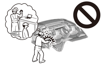
- While the auxiliary battery is connected, even if the power switch is off, the brake control system activates when the brake pedal is depressed or any door courtesy switch turns on. Therefore, when servicing the brake system components, do not operate the brake pedal or open/close the doors while the auxiliary battery is connected. (w/o vacuum brake booster)
-
Do not carry the brake booster with master cylinder assembly by the parts shown in the illustration.
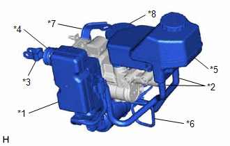
*1
No. 1 Skid Control ECU
*2
Reservoir Hose
*3
Master Cylinder Push Rod Clevis
*4
Boot
*5
Reservoir
*6
Brake Actuator Tube
*7
No. 1 Wire Clamp Bracket
*8
Brake Booster with Accumulator Pump Assembly
PROCEDURE
1. PRECAUTION
CAUTION:
Be sure to read precaution thoroughly before servicing.
Click here
![2021 - 2024 MY RAV4 RAV4 HV [08/2020 - ]; SUPPLEMENTAL RESTRAINT SYSTEMS: AIRBAG SYSTEM: PRECAUTION](/t3Portal/stylegraphics/info.gif)
NOTICE:
After turning the ignition switch off, waiting time may be required before disconnecting the cable from the negative (-) auxiliary battery terminal. Therefore, make sure to read the disconnecting the cable from the negative (-) auxiliary battery terminal notices before proceeding with work.
Click here
2. REMOVE BRAKE BOOSTER WITH MASTER CYLINDER ASSEMBLY
Click here
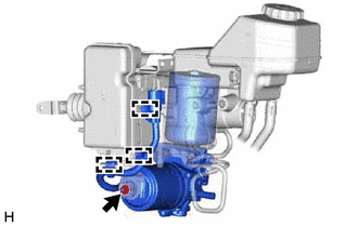
3. REMOVE BRAKE BOOSTER WITH ACCUMULATOR PUMP ASSEMBLY
|
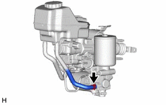
(a) Slide the clip and disconnect the No. 2 reservoir hose from the brake booster with accumulator pump assembly. |
|
|
(b) Using a union nut wrench, remove the brake actuator tube. NOTICE:
|
|
|
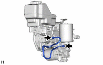
(c) Disengage the 3 clamps. |
|
(d) Remove the nut, brake booster with accumulator pump assembly, brake booster pump bushing and brake actuator case collar.
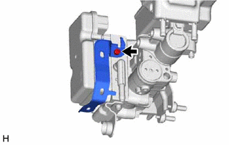
4. REMOVE NO. 2 WIRE CLAMP BRACKET
HINT:
Perform this procedure only when replacement of the No. 2 wire clamp bracket is necessary.
|
(a) Using a 5 mm long hexagon socket wrench, remove the bolt and No. 2 wire clamp bracket. |
|
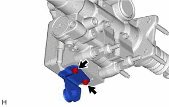
5. REMOVE NO. 1 BRAKE POWER SUPPLY BRACKET
HINT:
Perform this procedure only when replacement of the No. 1 brake power supply bracket is necessary.
|
(a) Using a 5 mm long hexagon socket wrench, remove the 2 bolts and No. 1 brake power supply bracket. |
|
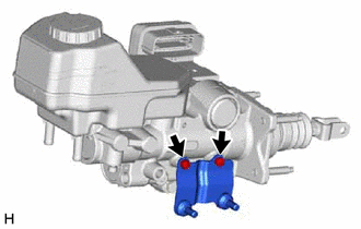
6. REMOVE NO. 2 BRAKE POWER SUPPLY BRACKET
HINT:
Perform this procedure only when replacement of the No. 2 brake power supply bracket is necessary.
|
(a) Using a 5 mm long hexagon socket wrench, remove the 2 bolts and No. 2 brake power supply bracket. |
|
|
|
|