| Last Modified: 01-30-2024 | 6.11:8.1.0 | Doc ID: RM1000000021HYC |
| Model Year Start: 2022 | Model: RAV4 HV | Prod Date Range: [12/2021 - 10/2022] |
| Title: A25A-FXS (BATTERY / CHARGING): CHARGING SYSTEM: ON-VEHICLE INSPECTION; 2022 MY RAV4 HV [12/2021 - 10/2022] | ||
ON-VEHICLE INSPECTION
CAUTION / NOTICE / HINT
The necessary procedures (adjustment, calibration, initialization, or registration) that must be performed after parts are removed and installed, or replaced when inspecting auxiliary battery are shown below.
Necessary Procedure After Parts Removed/Installed/Replaced
|
Replacement Part or Procedure |
Necessary Procedure |
Effect/Inoperative Function when Necessary Procedure not Performed |
Link |
|---|---|---|---|
|
*: When performing learning using the Techstream.
Click here
|
|||
|
Auxiliary battery terminal is disconnected/reconnected |
Perform steering sensor zero point calibration |
Lane control system |
|
|
Parking support brake system (for HV model)* |
|||
|
Pre-collision system |
|||
|
Memorize steering angle neutral point |
Parking assist monitor system |
|
|
|
Panoramic view monitor system (for HV model) |
|
||
|
Reset back door close position |
Power back door system (for HV model) |
|
|
|
Back door lock initialization |
Power door lock control system |
|
|
NOTICE:
After the ignition switch is turned off, the radio and display receiver assembly records various types of memory and settings. As a result, after turning the ignition switch off, be sure to wait for the time specified in the following table before disconnecting the cable from the negative (-) auxiliary battery terminal.
Waiting Time before Disconnecting Cable from Negative (-) Auxiliary Battery Terminal
|
System Name |
See Procedure |
|---|---|
|
Vehicle enrolled in Toyota Audio Multimedia system or safety connect system |
6 minutes |
|
Vehicle not enrolled in Toyota Audio Multimedia system and safety connect system |
1 minute |
PROCEDURE
1. CHECK AUXILIARY BATTERY
(a) Check that the auxiliary battery cables are connected to the correct terminals.
If they are not, connect them properly.
(b) Check the auxiliary battery for damage and deformation. If severe damage, deformation or leakage is found, replace the auxiliary battery.
2. CHECK AUXILIARY BATTERY VOLTAGE
(a) Turn the ignition switch off and turn on the high beam headlights for 30 seconds. This will remove the surface charge from the auxiliary battery.
(b) Measure the auxiliary battery voltage according to the value(s) in the table below.
|
Tester Connection |
Condition |
Specified Condition |
Result |
|---|---|---|---|
|
Positive (+) auxiliary battery terminal - Negative (-) auxiliary battery terminal |
20°C (68°F), Ignition switch off |
12.0 V or higher |
Auxiliary battery is OK |
|
12.0 V or less |
Recharge auxiliary battery |
3. RECHARGE AUXILIARY BATTERY
(a) Recharge the auxiliary battery.
HINT:
- Recharge the auxiliary battery according to the charger's instructions.
- Apply the appropriate charging current according to the type of auxiliary battery shown in the table below.
|
Charge Method |
Charging Current |
|---|---|
|
Normal |
Below 5 A |
|
Quick |
Below 15 A |
(b) Turn the ignition switch off and turn on the high beam headlights for 30 seconds. This will remove the surface charge from the auxiliary battery.
(c) Measure the auxiliary battery voltage according to the value(s) in the table below.
|
Tester Connection |
Condition |
Specified Condition |
Result |
|---|---|---|---|
|
Positive (+) auxiliary battery terminal - Negative (-) auxiliary battery terminal |
20°C (68°F), Ignition switch off |
12.0 V or higher |
Auxiliary battery is OK |
|
12.0 V or less |
Recharge auxiliary battery |
4. CHECK AUXILIARY BATTERY TERMINAL, FUSIBLE LINK AND FUSE
(a) Check that the auxiliary battery terminals are not loose or corroded.
Torque:
Positive (+) Auxiliary Battery Terminal :
5.4 N·m {55 kgf·cm, 48 in·lbf}
Negative (-) Auxiliary Battery Terminal :
5.4 N·m {55 kgf·cm, 48 in·lbf}
If a terminal is loose or corroded, tighten or clean the terminal.
(b) Measure the resistance of each fusible link and fuse for the auxiliary battery charging system.
Standard resistance:
Below 1 Ω
If the result is not as specified, replace the fusible link or fuse as necessary.
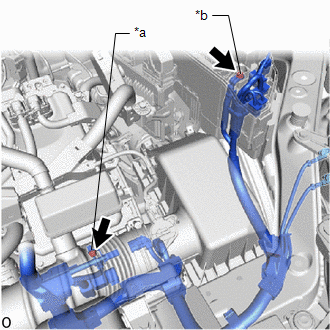
5. CHECK AMD TERMINAL
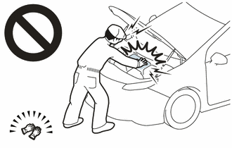
CAUTION:
-
Orange wire harnesses and connectors indicate high-voltage circuits. To prevent electric shock, always follow the procedure described in the repair manual.
Click here
![2019 - 2024 MY RAV4 RAV4 HV [11/2018 - ]; INTRODUCTION: REPAIR INSTRUCTION: PRECAUTION](/t3Portal/stylegraphics/info.gif)
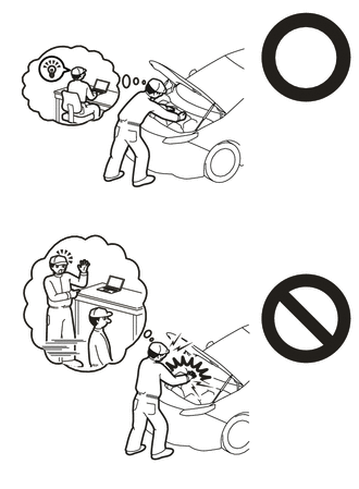
-
To prevent electric shock, wear insulated gloves when working on wire harnesses and components of the high voltage system.
(a) Remove the service plug grip.
Click here
(b) Check that the AMD terminal is connected securely, and there is no contact problem.
If there are any arc marks, replace the affected parts.
|
(c) Check that the nut for the AMD terminal is tightened to the specified torque. Torque: Inverter with Converter Assembly Side : 10 N·m {102 kgf·cm, 7 ft·lbf} No. 1 Engine Room Relay Block and No. 1 Junction Block Assembly Side : 8.0 N·m {82 kgf·cm, 71 in·lbf} If there are no arc marks and the AMD terminal connection is faulty, connect the AMD terminal securely. |
|
(d) Install the service plug grip.
Click here
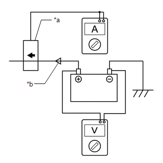
6. CHECK DC/DC CONVERTER FUNCTION
|
(a) Connect the AC/DC 400 A probe to the positive (+) auxiliary battery cable. |
|
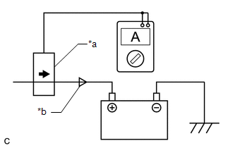
(b) Turn the ignition switch to on (READY) and leave the vehicle as is until the electric current flowing to the auxiliary battery becomes 10 A or less.
(c) Turn on the high beam headlights, and turn the blower motor switch to the HI position and the rear window defogger on.
|
(d) Measure the current and voltage according to the value(s) in the table below. Result:
If the result is not as specified, replace the inverter with converter assembly. |
|
|
|
|