| Last Modified: 01-30-2024 | 6.11:8.1.0 | Doc ID: RM1000000021GU8 |
| Model Year Start: 2022 | Model: RAV4 | Prod Date Range: [12/2021 - 10/2022] |
| Title: AUDIO / VIDEO: AUDIO AND VISUAL SYSTEM: Parking Brake Switch Circuit; 2022 MY RAV4 RAV4 HV [12/2021 - 10/2022] | ||
|
Parking Brake Switch Circuit |
DESCRIPTION
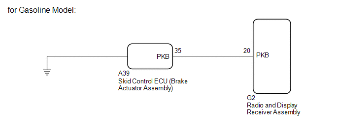
This circuit is from the skid control ECU (brake actuator assembly) to the radio and display receiver assembly.*1
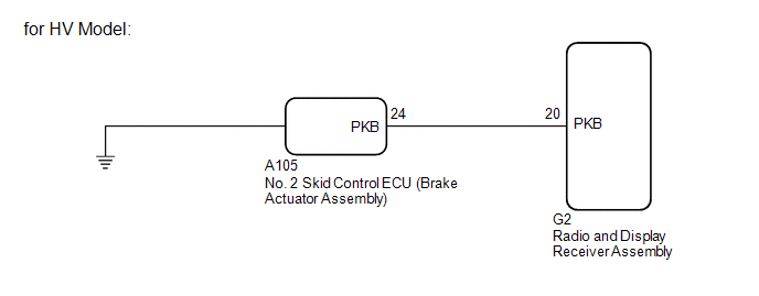
This circuit is from the No. 2 skid control ECU (brake actuator assembly) to the radio and display receiver assembly.*2
- *1: for Gasoline Model
- *2: for HV Model
WIRING DIAGRAM
PROCEDURE
|
1. |
CHECK BRAKE WARNING LIGHT |
(a) Check that the brake warning light comes on when the parking brake is applied and goes off when it is released.
OK:
The brake warning light operates as specified above.
|
Result |
Proceed to |
|---|---|
|
OK (for Gasoline Model) |
A |
|
OK (for HV Model) |
B |
|
NG (for Gasoline Model) |
C |
|
NG (for HV Model) |
D |
| B |

|
| C |
|
| D |
|
|

|
2. |
CHECK HARNESS AND CONNECTOR (SKID CONTROL ECU [BRAKE ACTUATOR ASSEMBLY] - RADIO AND DISPLAY RECEIVER ASSEMBLY) |
(a) Disconnect the G2 radio and display receiver assembly connector.
(b) Disconnect the A39 skid control ECU (brake actuator assembly) connector.
(c) Measure the resistance according to the value(s) in the table below.
Standard Resistance:
|
Tester Connection |
Condition |
Specified Condition |
|---|---|---|
|
G2-20 (PKB) - A39-35 (PKB) |
Always |
Below 1 Ω |
|
G2-20 (PKB) - Body ground |
Always |
10 kΩ or higher |
| OK |
|
PROCEED TO NEXT SUSPECTED AREA SHOWN IN PROBLEM SYMPTOMS TABLE |
| NG |
|
REPAIR OR REPLACE HARNESS OR CONNECTOR |
|
3. |
CHECK HARNESS AND CONNECTOR (NO. 2 SKID CONTROL ECU [BRAKE ACTUATOR ASSEMBLY] - RADIO AND DISPLAY RECEIVER ASSEMBLY) |
(a) Disconnect the G2 radio and display receiver assembly connector.
(b) Disconnect the A105 No. 2 skid control ECU (brake actuator assembly) connector.
(c) Measure the resistance according to the value(s) in the table below.
Standard Resistance:
|
Tester Connection |
Condition |
Specified Condition |
|---|---|---|
|
G2-20 (PKB) - A105-24 (PKB) |
Always |
Below 1 Ω |
|
G2-20 (PKB) - Body ground |
Always |
10 kΩ or higher |
| OK |
|
PROCEED TO NEXT SUSPECTED AREA SHOWN IN PROBLEM SYMPTOMS TABLE |
| NG |
|
REPAIR OR REPLACE HARNESS OR CONNECTOR |
|
|
|