- Perform "Reset Memory"
- Perform "Calibration"
| Last Modified: 05-08-2025 | 6.11:8.1.0 | Doc ID: RM1000000021FEI |
| Model Year Start: 2022 | Model: RAV4 | Prod Date Range: [12/2021 - ] |
| Title: DRIVE SHAFT / PROPELLER SHAFT: REAR DRIVE SHAFT ASSEMBLY: REMOVAL; 2022 - 2025 MY RAV4 RAV4 HV [12/2021 - ] | ||
REMOVAL
CAUTION / NOTICE / HINT
The necessary procedures (adjustment, calibration, initialization, or registration) that must be performed after parts are removed and installed, or replaced during rear drive shaft assembly removal/installation are shown below.
Necessary Procedures After Parts Removed/Installed/Replaced (for HV Model:)
|
Replaced Part or Performed Procedure |
Necessary Procedure |
Effect/Inoperative Function when Necessary Procedure not Performed |
Link |
|---|---|---|---|
|
Wheel alignment adjustment |
|
|
|
|
Suspension, tires, etc. |
Television camera assembly optical axis (Back camera position setting) |
Parking Assist Monitor System |
|
|
Parking assist ECU initialization |
Panoramic View Monitor System (for HV model) |
|
Necessary Procedures After Parts Removed/Installed/Replaced (for Gasoline Model:)
|
Replaced Part or Performed Procedure |
Necessary Procedure |
Effect/Inoperative Function when Necessary Procedure not Performed |
Link |
|---|---|---|---|
|
Rear wheel alignment adjustment |
Perform "Calibration" |
|
|
|
Suspension, tires, etc. |
Television camera assembly optical axis (Back camera position setting) |
Parking Assist Monitor System |
|
|
Parking assist ECU initialization |
Panoramic View Monitor System (for Gasoline model) |
|
HINT:
- Use the same procedure for the RH and LH sides.
- The procedure listed below is for the LH side.
PROCEDURE
1. REMOVE REAR WHEEL
Click here
![2019 - 2025 MY RAV4 RAV4 HV [11/2018 - ]; MAINTENANCE: TIRE AND WHEEL: REMOVAL](/t3Portal/stylegraphics/info.gif)
2. REMOVE REAR AXLE CARRIER
Click here
3. REMOVE REAR DRIVE SHAFT ASSEMBLY LH
|
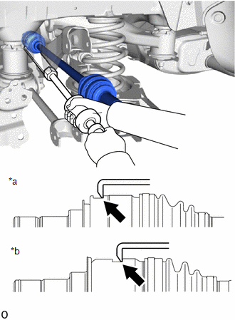
(a) Using SST, remove the rear drive shaft assembly LH from the rear differential carrier assembly. SST: 09520-01011 SST: 09520-20010 09521-02040 09521-02010 09521-02060 NOTICE:
|
|
4. REMOVE REAR DRIVE SHAFT INBOARD JOINT SHAFT SNAP RING LH
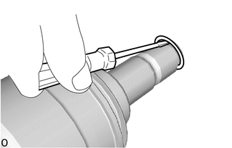
(a) Using a screwdriver, remove the rear drive shaft inboard joint shaft snap ring LH.
|
|
|