| Last Modified: 01-30-2024 | 6.11:8.1.0 | Doc ID: RM10000000214RE |
| Model Year Start: 2022 | Model: RAV4 | Prod Date Range: [12/2021 - ] |
| Title: BRAKE CONTROL / DYNAMIC CONTROL SYSTEMS: ELECTRONICALLY CONTROLLED BRAKE SYSTEM (w/o Vacuum Brake Booster): P05FF62; Brake Pressure Sensor / Brake Pedal Position Sensor Signal Compare Failure; 2022 - 2024 MY RAV4 RAV4 HV [12/2021 - ] | ||
|
DTC |
P05FF62 |
Brake Pressure Sensor / Brake Pedal Position Sensor Signal Compare Failure |
DESCRIPTION
If the No. 2 skid control ECU (brake actuator assembly) detects an inconsistency between the brake pedal stroke sensor assembly signal and reaction force pressure sensor signal, DTC P05FF62 is stored.
|
DTC No. |
Detection Item |
DTC Detection Condition |
Trouble Area |
MIL |
Note |
|---|---|---|---|---|---|
|
P05FF62 |
Brake Pressure Sensor / Brake Pedal Position Sensor Signal Compare Failure |
The difference between brake pedal stroke sensor assembly output value and reaction force pressure sensor output value is above the threshold for a certain period of time. |
|
Comes on |
|
MONITOR DESCRIPTION
The No. 2 skid control ECU (brake actuator assembly) monitors the ratio of output value of the brake pedal stroke sensor assembly and reaction force pressure sensor.
When in linear mode (switching solenoid (SSA) on), the brake pedal is being operated and the ratio of the output value of the brake pedal stroke sensor assembly and reaction force pressure sensor is outside the normal range, the No. 2 skid control ECU (brake actuator assembly) judges that the ratio of the output value of the brake pedal stroke sensor assembly and reaction force pressure sensor is abnormal and illuminates the MIL and stores this DTC.
MONITOR STRATEGY
|
Related DTCs |
P05FF: Brake position / reaction force pressure correlation |
|
Required Sensors/Components(Main) |
Brake actuator (brake booster with master cylinder assembly) Brake pedal stroke sensor assembly |
|
Required Sensors/Components(Related) |
No. 2 skid control ECU (brake actuator assembly) Brake actuator (brake booster with master cylinder assembly) Brake pedal stroke sensor assembly Stop light switch assembly |
|
Frequency of Operation |
Continuous |
|
Duration |
0.504 seconds |
|
MIL Operation |
Immediately |
|
Sequence of Operation |
None |
TYPICAL ENABLING CONDITIONS
| *: Electronically Controlled Brake System | |
|
Monitor runs whenever the following DTCs are not stored |
C0573 (Case 1): Accumulator pressure sensor lost communication C0573 (Case 2): Accumulator pressure sensor internal malfunction C0573 (Case 3): Accumulator pressure sensor invalid data C0574: Brake booster motor pressure sensor stuck C0577 (Case 1): Reaction force pressure sensor lost communication C0577 (Case 2): Reaction force pressure sensor internal malfunction C0577 (Case 3):(Reaction force pressure sensor invalid data C0578: Reaction force pressure sensor exceeded learning limit C0594: Brake booster motor performance C05A1 (Case 1): Servo pressure sensor lost communication C05A1 (Case 2): Servo pressure sensor internal malfunction C05A1 (Case 3): Servo pressure sensor invalid data C05A2: Servo pressure sensor exceeded learning limit C05C0: Brake pedal position sensor learning not complete C05C1: Brake pedal position sensor learning not complete C1100 (Case 1): Brake pedal position sensor voltage circuit/open C1100 (Case 2): Brake pedal position sensor invalid data C1103 (Case 1): Brake pedal position sensor voltage circuit/open C1103 (Case 2): Brake pedal position sensor invalid data C110F: Brake system voltage circuit low C121F: Brake system voltage performance C1256: Brake booster motor pressure too low C12FA: Brake system voltage power supply relay open circuit C12FB: Brake system voltage power supply relay circuit high C1345: Brake pressure control solenoid open current learning not complete C13D9: Brake pressure control solenoid pressure too low C13DA: Brake pressure control solenoid pressure too high C140F: Brake booster motor circuit open C141C (Case 1): Brake booster motor relay output shorted high C141C (Case 2): Brake booster motor freewheeling MOS output shorted high C141C (Case 3 to 10): Brake booster motor gate voltage output functional C141D: Brake booster motor open circuit C141E: Brake booster motor circuit high C1451: High pressure hydraulic tube air bleeding not complete C1496: Reaction force pressure sensor voltage circuit low C1497: Reaction force pressure sensor voltage circuit high C1498: Servo pressure sensor voltage circuit low C1499: Servo pressure sensor voltage circuit high C149E: Accumulator pressure sensor voltage circuit low C149F: Accumulator pressure sensor voltage circuit high C14B4: Reaction force pressure sensor intermittent/erratic C14C4: Servo pressure sensor intermittent/erratic C14C7 (Case 3 to 9): Brake system voltage circuit low C14CA: Brake system voltage open circuit C14D3: Accumulator pressure sensor intermittent/erratic C14DE: Brake system voltage circuit low C14EE: Brake pressure control solenoid "C" stuck on C14F3: Brake pressure control solenoid (SLA) circuit low C14F4: Brake pressure control solenoid (SLA) circuit high C14FC: Brake pressure control solenoid (SLR) circuit low C14FD: Brake pressure control solenoid (SLR) circuit high C1509: Brake pressure control solenoid (SSA) circuit low C150A: Brake pressure control solenoid (SSA) circuit high C150C: Brake pressure control solenoid "F" stuck on C150F: Brake pressure control solenoid (SGH) circuit low C1510: Brake pressure control solenoid (SGH) circuit high P057A: Brake pedal position sensor invalid data P057C: Brake pedal position sensor open circuit P057D: Brake pedal position sensor circuit high P057E: Brake pedal position sensor intermittent/erratic P05DB: Brake pedal position sensor invalid data P05DD: Brake pedal position sensor open circuit P05DE: Brake pedal position sensor circuit high P05DF: Brake pedal position sensor intermittent/erratic P05E0: Brake pedal position sensor "A"/"B" correlation U0129: Lost communication with ECB*_ECU (C-bus) |
|
All of the following conditions are met |
- |
|
Brake pedal position sensor fail |
Not detected |
|
Reaction force pressure sensor fail |
Not detected |
|
Brake-by-wire controlled mode |
On |
|
Brake pedal operation |
On |
TYPICAL MALFUNCTION THRESHOLDS
|
Following condition is met |
3 times or more |
|
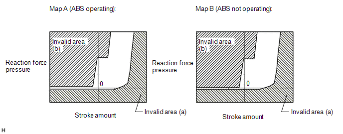
Ratio of the output value of the brake pedal stroke sensor assembly and reaction force pressure sensor |
Within the invalid area (a) or invalid area (b) of the following Map A or Map B |
COMPONENT OPERATING RANGE
|
All of the following conditions are met |
- |
|
Brake pedal position sensor fail |
Not detected |
|
Reaction force pressure sensor fail |
Not detected |
|
Brake-by-wire controlled mode |
On |
|
Brake pedal operation |
On |
|
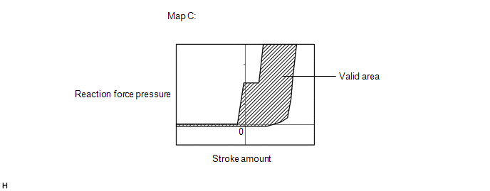
Ratio of the output value of the brake pedal stroke sensor assembly and reaction force pressure sensor |
Within the valid area of the Map C |
CONFIRMATION DRIVING PATTERN
NOTICE:
When performing the normal judgment procedure, make sure that the driver door is closed and is not opened at any time during the procedure.
HINT:
- After repair has been completed, clear the DTC and then check that the vehicle has returned to normal by performing the following All Readiness check procedure.
- When clearing the permanent DTCs, refer to the "CLEAR PERMANENT DTC" procedure.
- Connect the GTS to the DLC3.
- Turn the ignition switch to ON and turn the GTS on.
- Clear the DTCs (even if no DTCs are stored, perform the clear DTC procedure).
- Turn the ignition switch off.
- Turn the ignition switch to ON (READY) and turn the GTS on.
-
Depress the brake pedal 3 or more times. [*]
HINT:
[*]: Normal judgment procedure.
The normal judgment procedure is used to complete DTC judgment and also used when clearing permanent DTCs.
- Enter the following menus: Chassis / Brake/EPB / Utility / All Readiness.
-
Check the DTC judgment result.
HINT:
- If the judgment result shows NORMAL, the system is normal.
- If the judgment result shows ABNORMAL, the system has a malfunction.
- If the judgment result shows INCOMPLETE, perform driving pattern again.
CAUTION / NOTICE / HINT
NOTICE:
-
After replacing or reinstalling the brake pedal stroke sensor assembly, perform "Calibration" after performing "Reset Memory".
Click here
![2022 - 2024 MY RAV4 RAV4 HV [12/2021 - ]; BRAKE CONTROL / DYNAMIC CONTROL SYSTEMS: ELECTRONICALLY CONTROLLED BRAKE SYSTEM (w/o Vacuum Brake Booster): UTILITY](/t3Portal/stylegraphics/info.gif)
-
After replacing the No. 1 skid control ECU (brake booster with master cylinder assembly), perform "Calibration" after performing "Reset Memory".
Click here
- If the detection conditions for X21D2 are met 3 times in a row in the same trip, DTC P05FF62 is stored.
PROCEDURE
|
1. |
CUSTOMER PROBLEM ANALYSIS (CHECK CONDITION WHEN MALFUNCTION OCCURRED) AND FREEZE FRAME DATA |
(a) Interview the customer to check the vehicle conditions when the brake system warning light (red indicator) and brake system warning light (yellow indicator) illuminated.
(b) Using the GTS, check for Freeze Frame Data that is recorded when a DTC is stored.
Click here
Chassis > Brake Booster > Trouble Codes
HINT:
- Freeze Frame Data is only stored once when a DTC is stored.
- If other DTCs are output, repair any malfunctions related to those DTCs first, and then reproduce the conditions that caused DTC P05FF62 to be stored based on the interview with the customer.
|

|
2. |
READ VALUE USING GTS (BRAKE PEDAL STROKE SENSOR ASSEMBLY) |
(a) With the brake pedal released, confirm the brake pedal stroke sensor assembly output voltage.
Chassis > Brake Booster > Data List
|
Tester Display |
Measurement Item |
Range |
Normal Condition |
Diagnostic Note |
|---|---|---|---|---|
|
Stroke Sensor |
Brake pedal stroke sensor 1 |
Min.: 0.0 V Max.: 5.0 V |
Brake pedal released: 0.6 to 1.4 V |
Reading increases when brake pedal is depressed |
Chassis > Brake Booster > Data List
|
Tester Display |
|---|
|
Stroke Sensor |
OK:
0.6 to 1.4 V
| NG |

|
INSPECT/ADJUST INSTALLATION CONDITION OF BRAKE PEDAL STROKE SENSOR ASSEMBLY |
|
|
3. |
READ VALUE USING GTS (BRAKE PEDAL STROKE SENSOR ASSEMBLY) |
(a) Turn the ignition switch off.
(b) Mount a pedal effort gauge.
(c) Turn the ignition switch to ON (READY) and depress the brake pedal once.
HINT:
Depress the brake pedal after turning the ignition switch to ON (READY) to set the vehicle to linear mode (switching solenoid (SSA) on).
(d) Depress the brake pedal slowly and check the brake pedal stroke sensor assembly output voltages with respect to brake pedal depression force.
Chassis > Brake Booster > Data List
|
Tester Display |
Measurement Item |
Range |
Normal Condition |
Diagnostic Note |
|---|---|---|---|---|
|
Stroke Sensor |
Brake pedal stroke sensor 1 |
Min.: 0.0 V Max.: 5.0 V |
Brake pedal released: 0.6 to 1.4 V |
Reading increases when brake pedal is depressed |
Chassis > Brake Booster > Data List
|
Tester Display |
|---|
|
Stroke Sensor |
HINT:
Perform this procedure in linear mode (switching solenoid (SSA) on).
Standard Voltage:
|
Brake Effort [N (kgf, lbf)] |
Stroke Sensor [V] |
|---|---|
|
50 (5, 11.2) |
1.20 to 1.90 |
|
100 (10, 22.5) |
1.41 to 2.11 |
|
150 (15, 33.7) |
1.60 to 2.30 |
| NG |
|
REPLACE BRAKE PEDAL STROKE SENSOR ASSEMBLY
|
|
|
4. |
READ VALUE USING GTS (REACTION FORCE PRESSURE) |
(a) Depress the brake pedal slowly and check the reaction force pressure sensor output values with respect to brake pedal depression force.
Chassis > Brake Booster > Data List
|
Tester Display |
Measurement Item |
Range |
Normal Condition |
Diagnostic Note |
|---|---|---|---|---|
|
Reaction Force Pressure |
Pressure value of stroke simulator |
Min.: 0.00 MPa Max.: 24.48 MPa |
Brake pedal released: 0.00 to 1.53 MPa |
Brake pedal is being depressed: Changes in proportion to the depression force of the brake pedal |
Chassis > Brake Booster > Data List
|
Tester Display |
|---|
|
Reaction Force Pressure |
HINT:
Perform this procedure in linear mode (switching solenoid (SSA) on).
Standard Pressure:
|
Brake Effort [N (kgf, lbf)] |
Reaction Force Pressure [MPa] |
|---|---|
|
50 (5, 11.2) |
0.00 to 0.70 |
|
100 (10, 22.5) |
0.57 to 1.37 |
|
150 (15, 33.7) |
1.18 to 1.98 |
|
200 (20, 45.0) |
1.87 to 2.67 |
| NG |
|
CHECK AND REPAIR BRAKE FLUID LEAKS |
|
|
5. |
CLEAR DTC |
(a) Clear the DTCs.
Chassis > Brake Booster > Clear DTCs
(b) Turn the ignition switch off.
|
|
6. |
RECONFIRM DTC |
(a) Based on the Freeze Frame Data and interview with the customer, attempt to reproduce the conditions when the malfunction occurred.
(b) Check if the same DTC is output.
Chassis > Brake Booster > Trouble Codes
|
Result |
Proceed to |
|---|---|
|
DTC P05FF62 is not output. |
A |
|
DTC P05FF62 is output. |
B |
| A |
|
END |
| B |
|
REPLACE BRAKE BOOSTER WITH MASTER CYLINDER ASSEMBLY
|
|
|
|