| Last Modified: 01-30-2024 | 6.11:8.1.0 | Doc ID: RM10000000214R6 |
| Model Year Start: 2022 | Model: RAV4 | Prod Date Range: [12/2021 - ] |
| Title: BRAKE CONTROL / DYNAMIC CONTROL SYSTEMS: ELECTRONICALLY CONTROLLED BRAKE SYSTEM (w/o Vacuum Brake Booster): C15057E,C150B7E; Brake Pressure Control solenoid "E" Actuator Stuck On; 2022 - 2024 MY RAV4 RAV4 HV [12/2021 - ] | ||
|
DTC |
C15057E |
Brake Pressure Control solenoid "E" Actuator Stuck On |
|
DTC |
C150B7E |
Brake Pressure Control solenoid "F" Actuator Stuck On |
DESCRIPTION
The No. 1 skid control ECU (brake booster with master cylinder assembly) controls braking force according to the hybrid control system regenerative braking force and provides the hydraulic pressure necessary for operating the master cylinder and each wheel cylinder according to the servo pressure sensor.
HINT:
- Brake pressure control solenoid "E": Solenoid SSA
- Brake pressure control solenoid "F": Solenoid SGH
|
DTC No. |
Detection Item |
DTC Detection Condition |
Trouble Area |
MIL |
Note |
|---|---|---|---|---|---|
|
C15057E |
Brake Pressure Control solenoid "E" Actuator Stuck On |
SSA valve malfunction (stuck closed, etc.). |
Brake booster with master cylinder assembly |
Does not come on |
Output ECU: No. 1 skid control ECU (brake booster with master cylinder assembly) |
|
C150B7E |
Brake Pressure Control solenoid "F" Actuator Stuck On |
SGH valve malfunction (stuck closed, etc.). |
Brake booster with master cylinder assembly |
Comes on |
|
MONITOR DESCRIPTION
After the ignition switch is turned off, the No. 2 skid control ECU (brake actuator assembly) automatically performs a pressure increase check to detect malfunctions that would be difficult to detect during normal braking.
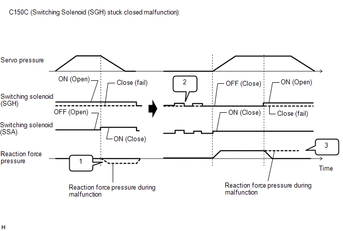
During the current trip when the vehicle is being driven at a certain speed or more and the following sequence is met, the No. 2 skid control ECU (brake actuator assembly) judges that the switching solenoid (SGH) is stuck closed and illuminates the MIL and stores this DTC.
- When the linear solenoid (SLR) is being operated to reduce servo pressure and the switching solenoid (SSA) and switching solenoid (SGH) are both closed, when the output piston is released, the volume of the reaction chamber expands, and because brake fluid is not introduced, a negative pressure is created.
- In the case of 1, if the negative pressure does not change for a certain amount of time, the No. 1 skid control ECU (brake booster with master cylinder assembly) repeatedly opens and closes the switching solenoid (SSA) and switching solenoid (SGH).
-
After 2 is performed, the linear solenoid (SLA) is operated to increase servo pressure and the reaction force pressure rises. When the switching solenoid (SGH) is instructed to be on (open) and there is a stuck closed malfunction, because the reaction force pressure does not reduce, when the reaction pressure exceeds a specific value for a certain amount of time, the No. 2 skid control ECU (brake actuator assembly) judges that there is a malfunction.
MONITOR STRATEGY
|
Related DTCs |
C150C: Brake pressure control solenoid "F" stuck on |
|
Required Sensors/Components(Main) |
No. 2 skid control ECU (brake actuator assembly) |
|
Required Sensors/Components(Related) |
Speed sensor No. 2 skid control ECU (brake actuator assembly) |
|
Frequency of Operation |
After ignition switch off |
|
Duration |
1.5 seconds: "B" in the table of Typical Malfunction Thresholds 6 seconds: "A" in the table of Typical Malfunction Thresholds |
|
MIL Operation |
Immediately |
|
Sequence of Operation |
None |
TYPICAL ENABLING CONDITIONS
| *: Electronically Controlled Brake System | |
|
Monitor runs whenever the following DTCs are not stored |
C0501: Wheel speed sensor (FL) range/performance C0502: Wheel speed sensor (FL) voltage circuit open C0503: Wheel speed sensor (FL) voltage circuit high C0504: Wheel speed sensor (FL) intermittent/erratic C0507: Wheel speed sensor (FR) range/performance C0508: Wheel speed sensor (FR) voltage circuit open C0509: Wheel speed sensor (FR) voltage circuit high C050A: Wheel speed sensor (FR) intermittent/erratic C050D: Wheel speed sensor (RL) range/performance C050E: Wheel speed sensor (RL) voltage circuit open C050F: Wheel speed sensor (RL) voltage circuit high C0510: Wheel speed sensor (RL) intermittent/erratic C0513: Wheel speed sensor (RR) range/performance C0514: Wheel speed sensor (RR) voltage circuit open C0515: Wheel speed sensor (RR) voltage circuit high C0516: Wheel speed sensor (RR) intermittent/erratic C051C: Acceleration sensor range/performance C051D: Acceleration sensor missing calibration C051E: Acceleration sensor intermittent/erratic C0520 (Case 1): Acceleration sensor (GL1, GL2) out of range C0520 (Case 2): Acceleration sensor internal malfunction C052B: ABS pump motor performance C052D: ABS pump motor circuit high C052E: ABS pump motor open circuit C053D: Pressure sensor invalid data C0540 (Case 1): Pressure sensor verify communication C0540 (Case 2 to 4): Pressure sensor range check C055B: ABS pump motor voltage circuit low C056B: Pressure sensor intermittent/erratic C0573 (Case 1): Accumulator pressure sensor lost communication C0573 (Case 2): Accumulator pressure sensor internal malfunction C0573 (Case 3): Accumulator pressure sensor invalid data C0574: Brake booster motor pressure sensor stuck C0577 (Case 1): Reaction force pressure sensor lost communication C0577 (Case 2): Reaction force pressure sensor internal malfunction C0577 (Case 3): Reaction force pressure sensor invalid data C0578: Reaction force pressure sensor exceeded learning limit C0594: Brake booster motor performance C0597: (Case 1) ABS hold solenoid circuit stuck C0597: (Case 2 to 5) ABS hold solenoid performance C05A1 (Case 1): Servo pressure sensor lost communication C05A1 (Case 2): Servo pressure sensor internal malfunction C05A1 (Case 3): Servo pressure sensor invalid data C05A2: Servo pressure sensor exceeded learning limit C05C0: Brake pedal position sensor learning not complete C05C1: Brake pedal position sensor learning not complete C1100 (Case 1): Brake pedal position sensor voltage circuit/open C1100 (Case 2): Brake pedal position sensor invalid data C1103 (Case 1): Brake pedal position sensor voltage circuit/open C1103 (Case 2): Brake pedal position sensor invalid data C110F: Brake system voltage circuit low C1202: Reservoir level too low C120F: Reservoir level switch open circuit C121F: Brake system voltage performance C122E: Pressure sensor input out of range low C122F: Pressure sensor input out of range high C1240: Yaw rate and acceleration sensor incorrect C1241: Brake system voltage input out of range low C124A: Identification signal C1256: Brake booster motor pressure too low C12A7: ABS hold solenoid (FL) circuit low C12A8: ABS hold solenoid (FL) circuit high C12B2: ABS release solenoid (FL) circuit low C12B3: ABS release solenoid (FL) circuit high C12BD: ABS hold solenoid (FR) circuit low C12BE: ABS hold solenoid (FR) circuit high C12C8: ABS release solenoid (FR) circuit low C12C9: ABS release solenoid (FR) circuit high C12D3: ABS hold solenoid (RL) circuit low C12D4: ABS hold solenoid (RL) circuit high C12DE: ABS release solenoid (RL) circuit low C12DF: ABS release solenoid (RL) circuit high C12E9: ABS hold solenoid (RR) circuit low C12EA: ABS hold solenoid (RR) circuit high C12F4: ABS release solenoid (RR) circuit low C12F5: ABS release solenoid (RR) circuit high C12F6: ABS hold solenoid other functional C12F7: ABS hold solenoid other functional C12FA: Brake system voltage power supply relay open circuit C12FB: Brake system voltage power supply relay circuit high C1345: Brake pressure control solenoid open current learning not complete C137C: Brake system voltage input out of range low C137D: Brake system voltage input out of range high C13BF: SM solenoid other functional C13C2: SM1 solenoid circuit low C13C3: SM1 solenoid circuit high C13CB: SM2 solenoid circuit low C13CC: SM2 solenoid circuit high C13D9: Brake pressure control solenoid pressure too low C13DA: Brake pressure control solenoid pressure too high C140F: Brake booster motor circuit open C141C (Case 1): Brake booster motor relay output shorted high C141C (Case 2): Brake booster motor freewheeling MOS output shorted high C141C (Case 3 to 10): Brake booster motor gate voltage output functional C141D: Brake booster motor open circuit C141E: Brake booster motor circuit high C1427: ABS pump motor stuck C143B: Brake system voltage solenoid relay stuck C143C: Brake system voltage open circuit C1451: High pressure hydraulic tube air bleeding not complete C1496: Reaction force pressure sensor voltage circuit low C1497: Reaction force pressure sensor voltage circuit high C1498: Servo pressure sensor voltage circuit low C1499: Servo pressure sensor voltage circuit high C149E: Accumulator pressure sensor voltage circuit low C149F: Accumulator pressure sensor voltage circuit high C14B4: Reaction force pressure sensor intermittent/erratic C14C4: Servo pressure sensor intermittent/erratic C14C7: Brake system voltage circuit low C14CA: Brake system voltage open circuit C14D3: Accumulator pressure sensor intermittent/erratic C14D7: Acceleration sensor voltage circuit/open C14DE: Brake system voltage circuit low C14E1: Wheel speed sensor (FL) voltage circuit low C14E4: Wheel speed sensor (FR) voltage circuit low C14E7: Wheel speed sensor (RL) voltage circuit low C14EA: Wheel speed sensor (RR) voltage circuit low C14EE: Brake pressure control solenoid "A" stuck on C14F3: Brake pressure control solenoid SLA circuit low C14F4: Brake pressure control solenoid SLA circuit high C14FC: Brake pressure control solenoid SLR circuit low C14FD: Brake pressure control solenoid SLR circuit high C1509: Brake pressure control solenoid SSA circuit low C150A: Brake pressure control solenoid SSA circuit high C150F: Brake pressure control solenoid SGH circuit low C1510: Brake pressure control solenoid SGH circuit high P057A: Brake pedal position sensor invalid data P057C: Brake pedal position sensor open circuit P057D: Brake pedal position sensor circuit high P057E: Brake pedal position sensor intermittent/erratic P05DB: Brake pedal position sensor invalid data P05DD: Brake pedal position sensor open circuit P05DE: Brake pedal position sensor circuit high P05DF: Brake pedal position sensor intermittent/erratic P05E0: Brake pedal position sensor "A"/"B" correlation P05FF: Brake position / reaction force pressure correlation U0074 (Case 1): Late communication with multi-axis acceleration sensor module U0110: Lost communication with drive motor control module "A" U0125: Lost communication with multi-axis acceleration sensor module U0129: Lost communication with ECB*_ECU (C-bus) U025E: Lost communication with electronic brake booster control unit (C-Bus) U0293: Lost communication with HV (C-Bus) U1107: Lost communication with collation ECU U1150: Lost communication with HV (P-Bus) |
|
All of the following conditions are met |
- |
|
Ignition switch |
Off |
|
Max vehicle speed in this trip |
Higher than 3 km/h (1.864 mph) |
|
Reaction force pressure sensor fail |
Not detected |
|
Servo pressure sensor fail |
Not detected |
|
Brake-by-wire controlled mode |
On |
|
Brake fluid temperature |
Higher than 0°C (32°F) |
|
Up/downstream communication |
Valid |
|
History of shift range when the ignition switch changes into off |
P range |
|
History of vehicle running after ignition switch off |
Off |
TYPICAL MALFUNCTION THRESHOLDS
|
Both of the following conditions are met |
A and B |
|
A. Either of the following conditions is met |
- |
|
Reaction force pressure decrease (a) |
0.03 MPa (0.3 kgf/cm2, 4.4 psi) or more |
|
Reaction force pressure (b) |
Less than -0.6 MPa (-6.1 kgf/cm2, -87 psi) |
|
B. Reaction force pressure after malfunction criteria (a) or (b) is met |
0.2 MPa (2 kgf/cm2, 29 psi) or more |
COMPONENT OPERATING RANGE
|
All of the following conditions are met |
A, B, C, D, E, F, G, H, I and J |
|
A. Ignition switch |
Off |
|
B. Max vehicle speed in this trip |
Higher than 3 km/h (1.864 mph) |
|
C. Reaction force pressure sensor fail |
Not detected |
|
D. Servo pressure sensor fail |
Not detected |
|
E. Brake-by-wire controlled mode |
On |
|
F. Brake fluid temperature |
Higher than 0°C (32°F) |
|
G. Up/downstream communication |
Valid |
|
H. History of shift range when the ignition switch changes into off |
P range |
|
I. History of vehicle running after ignition switch off |
Off |
|
J. Either of the following conditions is met |
a or b |
|
a. Both of the following conditions are met |
- |
|
Reaction force pressure decrease (a) |
0.03 MPa (0.3 kgf/cm2, 4.4 psi) or more |
|
Reaction force pressure (b) |
Less than -0.6 MPa (-6.1 kgf/cm2, -87 psi) |
|
b. Reaction force pressure after malfunction criteria (a) or (b) is met |
0.2 MPa (2 kgf/cm2, 29 psi) or more |
CONFIRMATION DRIVING PATTERN
NOTICE:
When performing the normal judgment procedure, make sure that the driver door is closed and is not opened at any time during the procedure.
HINT:
- After repair has been completed, clear the DTC and then check that the vehicle has returned to normal by performing the following All Readiness check procedure.
- When clearing the permanent DTCs, refer to the "CLEAR PERMANENT DTC" procedure.
- Connect the GTS to the DLC3.
- Turn the ignition switch to ON and turn the GTS on.
- Clear the DTCs (even if no DTCs are stored, perform the clear DTC procedure).
- Turn the ignition switch off.
- Turn the ignition switch to ON (READY) and turn the GTS on.
- Drive the vehicle at 3 km/h (2 mph) or more for 1 second. [*1]
- Turn the ignition switch off. [*2]
- Wait 4 minutes. [*3]
- Turn the ignition switch to ON (READY). [*4]
-
Depress the brake pedal for 2 seconds, release it and wait 1 second. [*5]
HINT:
[*1] to [*5]: Normal judgment procedure.
The normal judgment procedure is used to complete DTC judgment and also used when clearing permanent DTCs.
- Enter the following menus: Chassis / Brake/EPB / Utility / All Readiness.
-
Check the DTC judgment result.
HINT:
- If the judgment result shows NORMAL, the system is normal.
- If the judgment result shows ABNORMAL, the system has a malfunction.
- If the judgment result shows INCOMPLETE, perform driving pattern again.
CAUTION / NOTICE / HINT
NOTICE:
After replacing the No. 1 skid control ECU (brake booster with master cylinder assembly), perform "Calibration" after performing "Reset Memory".
Click here
![2022 - 2024 MY RAV4 RAV4 HV [12/2021 - ]; BRAKE CONTROL / DYNAMIC CONTROL SYSTEMS: ELECTRONICALLY CONTROLLED BRAKE SYSTEM (w/o Vacuum Brake Booster): UTILITY](/t3Portal/stylegraphics/info.gif)
PROCEDURE
|
1. |
CHECK DTC |
(a) Check the DTCs that are output.
Chassis > Brake Booster > Trouble Codes
Chassis > Brake/EPB > Trouble Codes
|
Result |
Proceed to |
|---|---|
|
Only DTCs C15057E and/or C150B7E are output. |
A |
|
DTCs other than C15057E and/or C150B7E are output. |
B |
| A |

|
REPLACE BRAKE BOOSTER WITH MASTER CYLINDER ASSEMBLY
|
| B |
|
REPAIR CIRCUITS INDICATED BY OUTPUT DTCS |
|
|
|