| Last Modified: 01-30-2024 | 6.11:8.1.0 | Doc ID: RM10000000214R1 |
| Model Year Start: 2022 | Model: RAV4 | Prod Date Range: [12/2021 - ] |
| Title: BRAKE CONTROL / DYNAMIC CONTROL SYSTEMS: ELECTRONICALLY CONTROLLED BRAKE SYSTEM (w/o Vacuum Brake Booster): C14D71C; Multi-axis Acceleration Sensor Module "A" Supply Voltage Circuit Voltage Out of Range; 2022 - 2024 MY RAV4 RAV4 HV [12/2021 - ] | ||
|
DTC |
C14D71C |
Multi-axis Acceleration Sensor Module "A" Supply Voltage Circuit Voltage Out of Range |
DESCRIPTION
The airbag ECU assembly has a built-in acceleration sensor.
This DTC is stored when the No. 2 skid control ECU (brake actuator assembly) receives a sensor supply voltage malfunction signal from the airbag ECU assembly.
This DTC may be stored due to an intermittent low power source voltage.
|
DTC No. |
Detection Item |
DTC Detection Condition |
Trouble Area |
MIL |
Note |
|---|---|---|---|---|---|
|
C14D71C |
Multi-axis Acceleration Sensor Module "A" Supply Voltage Circuit Voltage Out of Range |
When the +BS terminal voltage is from 9.5 to 17.4 V at a vehicle speed exceeding 3 km/h (2 mph), an acceleration sensor power source malfunction signal is received for 10 seconds or more. |
|
Comes on |
|
MONITOR DESCRIPTION
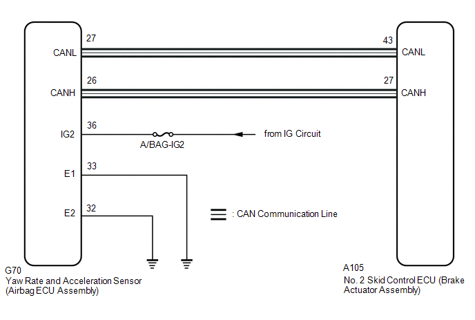
The No. 2 skid control ECU (brake actuator assembly) receives valid or invalid information from the yaw rate and acceleration sensor (airbag ECU assembly) power supply voltage via CAN communication. When the vehicle is being driven and an invalid yaw rate and acceleration sensor (airbag ECU assembly) power supply voltage is received via CAN communication for a certain amount of time, the No. 2 skid control ECU (brake actuator assembly) judges that the power supply voltage of the yaw rate and acceleration sensor (airbag ECU assembly) is abnormal and illuminates the MIL and stores this DTC.
MONITOR STRATEGY
|
Related DTCs |
C14D7: Acceleration sensor voltage circuit/open |
|
Required Sensors/Components(Main) |
Yaw rate and acceleration sensor (airbag ECU assembly) |
|
Required Sensors/Components(Related) |
Speed sensor |
|
Frequency of Operation |
Continuous |
|
Duration |
10 seconds |
|
MIL Operation |
Immediately |
|
Sequence of Operation |
None |
TYPICAL ENABLING CONDITIONS
|
Monitor runs whenever the following DTCs are not stored |
C1241: Brake system voltage input out of range low C137D: Brake system voltage input out of range high U0125: Lost communication with multi-axis acceleration sensor module |
|
All of the following conditions are met |
- |
|
Communication status with yaw rate and acceleration sensor (airbag ECU assembly) |
Valid |
|
Vehicle speed |
Higher than 3 km/h (1.86 mph) |
|
IG1 |
On |
|
+BS voltage |
9.5 V or more, and 17.4 V or less |
TYPICAL MALFUNCTION THRESHOLDS
|
Sensor power supply voltage (IG) |
Invalid |
COMPONENT OPERATING RANGE
|
Both of the following conditions are met |
- |
|
Communication status with yaw rate and acceleration sensor (airbag ECU assembly) |
Valid |
|
Sensor power supply voltage (IG) |
Valid |
CONFIRMATION DRIVING PATTERN
NOTICE:
When performing the normal judgment procedure, make sure that the driver door is closed and is not opened at any time during the procedure.
HINT:
- After repair has been completed, clear the DTC and then check that the vehicle has returned to normal by performing the following All Readiness check procedure.
- When clearing the permanent DTCs, refer to the "CLEAR PERMANENT DTC" procedure.
- Connect the GTS to the DLC3.
- Turn the ignition switch to ON and turn the GTS on.
- Clear the DTCs (even if no DTCs are stored, perform the clear DTC procedure).
- Turn the ignition switch off.
- Turn the ignition switch to ON (READY) and turn the GTS on.
-
Drive the vehicle at a speed of 5 km/h (3 mph) or more for 10 seconds or more. [*]
HINT:
[*]: Normal judgment procedure.
The normal judgment procedure is used to complete DTC judgment and also used when clearing permanent DTCs.
- Enter the following menus: Chassis / Brake/EPB / Utility / All Readiness.
-
Check the DTC judgment result.
HINT:
- If the judgment result shows NORMAL, the system is normal.
- If the judgment result shows ABNORMAL, the system has a malfunction.
- If the judgment result shows INCOMPLETE, perform driving pattern again.
WIRING DIAGRAM
CAUTION / NOTICE / HINT
NOTICE:
- Inspect the fuses for circuits related to this system before performing the following procedure.
-
After replacing or reinstalling the yaw rate and acceleration sensor (airbag ECU assembly), perform "Calibration" after performing "Reset Memory".
Click here
![2022 - 2024 MY RAV4 RAV4 HV [12/2021 - ]; BRAKE CONTROL / DYNAMIC CONTROL SYSTEMS: ELECTRONICALLY CONTROLLED BRAKE SYSTEM (w/o Vacuum Brake Booster): UTILITY](/t3Portal/stylegraphics/info.gif)
PROCEDURE
|
1. |
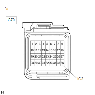
CHECK HARNESS AND CONNECTOR (IG2 TERMINAL) |
NOTICE:
-
After turning the ignition switch off, waiting time may be required before disconnecting the cable from the auxiliary battery terminal. Therefore, make sure to read the disconnecting the cable from the auxiliary battery terminal notice before proceeding with work
Click here
-
When disconnecting the cable, some systems need to be initialized after the cable is reconnected.
Click here
|
(a) Make sure that there is no looseness at the locking part and the connecting part of the connectors. OK: The connector is securely connected. |
|
(b) Disconnect the G70 yaw rate and acceleration sensor (airbag ECU assembly) connector.
(c) Check both the connector case and the terminals for deformation and corrosion.
OK:
No deformation or corrosion.
(d) Turn the ignition switch to ON.
(e) Measure the voltage according to the value(s) in the table below.
Standard Voltage:
|
Tester Connection |
Condition |
Specified Condition |
|---|---|---|
|
G70-36 (IG2) - Body ground |
Ignition switch ON |
11 to 14 V |
| NG |

|
REPAIR OR REPLACE HARNESS OR CONNECTOR |
|

|
2. |
CHECK HARNESS AND CONNECTOR (GND TERMINAL) |
(a) Turn the ignition switch off.
(b) Measure the resistance according to the value(s) in the table below.
Standard Resistance:
|
Tester Connection |
Condition |
Specified Condition |
|---|---|---|
|
G70-33 (E1) - Body ground |
1 minute or more after disconnecting the cable from the negative (-) auxiliary battery terminal |
Below 1 Ω |
|
G70-32 (E2) - Body ground |
1 minute or more after disconnecting the cable from the negative (-) auxiliary battery terminal |
Below 1 Ω |
| NG |
|
REPAIR OR REPLACE HARNESS OR CONNECTOR |
|
|
3. |
CLEAR DTC |
(a) Reconnect the G70 yaw rate and acceleration sensor (airbag ECU assembly) connector.
(b) Clear the DTCs.
Chassis > Brake/EPB > Clear DTCs
(c) Turn the ignition switch off.
|
|
4. |
RECONFIRM DTC |
(a) Based on the Freeze Frame Data and interview with the customer, attempt to reproduce the conditions when the malfunction occurred.
(b) Check if the same DTC is output.
Chassis > Brake/EPB > Trouble Codes
|
Result |
Proceed to |
|---|---|
|
DTC C14D71C is not output. |
A |
|
DTC C14D71C is output. |
B |
| A |
|
| B |
|
REPLACE AIRBAG ECU ASSEMBLY
|
|
|
|