| Last Modified: 01-30-2024 | 6.11:8.1.0 | Doc ID: RM10000000214QD |
| Model Year Start: 2022 | Model: RAV4 | Prod Date Range: [12/2021 - ] |
| Title: BRAKE CONTROL / DYNAMIC CONTROL SYSTEMS: ELECTRONICALLY CONTROLLED BRAKE SYSTEM (w/o Vacuum Brake Booster): C12F812,C12F814; ECB Solenoid Control "A" Circuit Short to Battery; 2022 - 2024 MY RAV4 RAV4 HV [12/2021 - ] | ||
|
DTC |
C12F812 |
ECB Solenoid Control "A" Circuit Short to Battery |
|
DTC |
C12F814 |
ECB Solenoid Control "A" Circuit Short to Ground or Open |
DESCRIPTION
The main relay is built into the No. 1 skid control ECU (brake booster with master cylinder assembly).
The main relay supplies power to the switching solenoid and the linear solenoid.
The main relay remains on for approximately 4 minutes after the ignition switch is turned off and the input of brake pedal operation signals stops, and supplies power to the system to keep it ready to operate.
|
DTC No. |
Detection Item |
DTC Detection Condition |
Trouble Area |
MIL |
Note |
|---|---|---|---|---|---|
|
C12F812 |
ECB Solenoid Control "A" Circuit Short to Battery |
The BS terminal voltage is 3.5 V or more for 4.5 seconds or more, when operation of the main relay is requested. |
|
Comes on |
|
|
C12F814 |
ECB Solenoid Control "A" Circuit Short to Ground or Open |
Either of the following is detected:
|
|
Comes on |
|
C12F814 DTC Detection Conditions
|
Vehicle Condition |
|||
|---|---|---|---|
|
Pattern 1 |
Pattern 2 |
||
|
Diagnosis Condition |
When the ignition switch is turned to ON (READY) |
○ |
- |
|
When the IG1 terminal voltage is 9.5 V or more |
○ |
- |
|
|
When the ignition switch is off |
- |
○ |
|
|
Malfunction Status |
The BS terminal voltage is less than 3.8 V and operation of the main relay is requested |
○ |
○ |
|
Detection Time |
0.05 seconds or more. |
0.05 seconds or more. |
|
|
Number of Trips |
1 trip |
1 trip |
|
HINT:
DTC will be output when conditions for either of the patterns in the table above are met.
MONITOR DESCRIPTION
The No. 2 skid control ECU (brake actuator assembly) monitors the voltage at BS terminal.
When the main relay is instructed to be on and the voltage at BS terminal is within the range of an open circuit malfunction (voltage is practically equal to that when off), or when the main relay is instructed to be off and the voltage of the BS terminal is within the range of a short circuit malfunction (voltage is practically equal to that when on), an open circuit or short circuit is judged respectively and the MIL is illuminated and stores a DTC.
MONITOR STRATEGY
|
Related DTCs |
C12FA: Brake system voltage power supply relay open circuit C12FB: Brake system voltage power supply relay circuit high |
|
Required Sensors/Components(Main) |
No. 2 skid control ECU (brake actuator assembly) |
|
Required Sensors/Components(Related) |
No. 2 skid control ECU (brake actuator assembly) |
|
Frequency of Operation |
Continuous |
|
Duration |
0.054 seconds: C12FA (Case 1 and 2) 0.204 seconds: C12FA (Case 3) 4.5 seconds: C12FB |
|
MIL Operation |
Immediately |
|
Sequence of Operation |
None |
TYPICAL ENABLING CONDITIONS
C12FA (Case 1)
|
Monitor runs whenever the following DTCs are not stored |
C14C7 (Case 3 to 9): Brake system voltage circuit low |
|
All of the following conditions are met |
A, B, C and D |
|
A. Ignition switch |
Off |
|
B. +BS (linear) effective invalidity |
Valid |
|
C. Command to brake pressure control solenoid power supply relay |
On |
|
D. Either of the following conditions is met |
- |
|
Brake system voltage 1 |
Higher than 7.3 V |
|
Main relay on experience |
Unavailable |
C12FA (Case 2)
|
Monitor runs whenever the following DTCs are not stored |
C14C7 (Case 3 to 9): Brake system voltage circuit low |
|
All of the following conditions are met |
A, B, C and D |
|
A. Ignition switch |
On (READY) |
|
B. +BS (linear) effective invalidity |
Valid |
|
C. Command to brake pressure control solenoid power supply relay |
On |
|
D. Either of the following conditions is met |
a or b |
|
a. Both of the following conditions are met |
- |
|
Brake system voltage 1 |
Higher than 7.3 V |
|
IG1 voltage |
Higher than 9.5 V |
|
b. Main relay on experience |
Unavailable |
C12FA (Case 3)
|
Monitor runs whenever the following DTCs are not stored |
C14C7 (Case 3 to 9): Brake system voltage circuit low |
|
Both of the following conditions are met |
- |
|
Solenoid relay |
On |
|
Brake system voltage 1 |
Higher than 7.3 V |
C12FB (Case 1)
|
Monitor runs whenever the following DTCs are not stored |
None |
|
Both of the following conditions are met |
- |
|
+BS (linear) effective invalidity |
Valid |
|
Command to brake pressure control solenoid power supply relay |
Off |
C12FB (Case 2)
|
Monitor runs whenever the following DTCs are not stored |
None |
|
Solenoid relay |
Off |
TYPICAL MALFUNCTION THRESHOLDS
C12FA (Case 1 and 2)
|
Power supply for solenoid voltage |
Less than 3.3 V |
C12FA (Case 3)
|
Power supply for solenoid voltage |
Less than 6.0 V |
C12FB (Case 1)
|
Power supply for solenoid voltage |
3.3 V or more |
C12FB (Case 2)
|
Power supply for solenoid voltage |
6.0 V or more |
COMPONENT OPERATING RANGE
C12FA (Case 1 and 2) and C12FB (Case 1)
|
Both of the following conditions are met |
A and B |
|
A. All of the following conditions are met at the ECU status (last IG ON timing final) |
- |
|
Brake system voltage fail (C12FA, C12FB) |
Not detected |
|
Brake booster motor fail (C141C, C141D, C141E, C141F) |
Not detected |
|
Brake pressure control solenoid fail (C14F4, C14FD, C150A, C1510) |
Not detected |
|
B. All of the following conditions are met at the ECU status (pre main) |
- |
|
Brake system voltage fail (C121F, C12FA, C12FB) |
Not detected |
|
Brake booster motor fail (C141C) |
Not detected |
|
Brake pressure control solenoid fail (C14F3, C14F4, C14FC, C14FD, C1509, C150A, C150F, C1510) |
Not detected |
C12FA (Case 3)
|
All of the following conditions are met |
A, B, C and D |
|
A. Solenoid relay |
On |
|
B. Brake system voltage 1 |
Higher than 7.3 V |
|
C. All of the following conditions are met at the ECU status (last IG ON timing final) |
- |
|
Brake system voltage fail (C12FA, C12FB) |
Not detected |
|
Brake booster motor fail (C141C, C141D, C141E, C141F) |
Not detected |
|
Brake pressure control solenoid fail (C14F4, C14FD, C150A, C1510) |
Not detected |
|
D. All of the following conditions are met at the ECU status (pre main) |
- |
|
Brake system voltage fail (C121F, C12FA, C12FB) |
Not detected |
|
Brake booster motor fail (C141C) |
Not detected |
|
Brake pressure control solenoid fail (C14F3, C14F4, C14FC, C14FD, C1509, C150A, C150F, C1510) |
Not detected |
C12FB (Case 2)
|
All of the following conditions are met |
A, B and C |
|
A. Solenoid relay |
Off |
|
B. All of the following conditions are met at the ECU status (last IG ON timing final) |
- |
|
Brake system voltage fail (C12FA, C12FB) |
Not detected |
|
Brake booster motor fail (C141C, C141D, C141E, C141F) |
Not detected |
|
Brake pressure control solenoid fail (C14F4, C14FD, C150A, C1510) |
Not detected |
|
C. All of the following conditions are met at the ECU status (pre main) |
- |
|
Brake system voltage fail (C121F, C12FA, C12FB) |
Not detected |
|
Brake booster motor fail (C141C) |
Not detected |
|
Brake pressure control solenoid fail (C14F3, C14F4, C14FC, C14FD, C1509, C150A, C150F, C1510) |
Not detected |
CONFIRMATION DRIVING PATTERN
NOTICE:
When performing the normal judgment procedure, make sure that the driver door is closed and is not opened at any time during the procedure.
HINT:
- After repair has been completed, clear the DTC and then check that the vehicle has returned to normal by performing the following All Readiness check procedure.
- When clearing the permanent DTCs, refer to the "CLEAR PERMANENT DTC" procedure.
- Connect the GTS to the DLC3.
- Turn the ignition switch to ON and turn the GTS on.
- Clear the DTCs (even if no DTCs are stored, perform the clear DTC procedure).
- Turn the ignition switch off.
- Turn the ignition switch to ON (READY) and turn the GTS on.
-
Wait for 5 seconds or more. [*]
HINT:
[*]: Normal judgment procedure.
The normal judgment procedure is used to complete DTC judgment and also used when clearing permanent DTCs.
- Enter the following menus: Chassis / Brake/EPB / Utility / All Readiness.
-
Check the DTC judgment result.
HINT:
- If the judgment result shows NORMAL, the system is normal.
- If the judgment result shows ABNORMAL, the system has a malfunction.
- If the judgment result shows INCOMPLETE, perform driving pattern again.
WIRING DIAGRAM
Refer to DTC C110E14.
Click here
![2022 - 2024 MY RAV4 RAV4 HV [12/2021 - ]; BRAKE CONTROL / DYNAMIC CONTROL SYSTEMS: ELECTRONICALLY CONTROLLED BRAKE SYSTEM (w/o Vacuum Brake Booster): C110E14; Brake Booster Motor "A" Supply Voltage Circuit Short to Ground or Open+](/t3Portal/stylegraphics/info.gif)
CAUTION / NOTICE / HINT
NOTICE:
- Inspect the fuses for circuits related to this system before performing the following procedure.
-
After replacing the No. 1 skid control ECU (brake booster with master cylinder assembly), perform "Calibration" after performing "Reset Memory".
Click here
PROCEDURE
|
1. |
PERFORM ACTIVE TEST USING GTS (MAIN RELAY) |
(a) Perform the Active Test and operate the main relay.
(b) Monitor the value of BS Voltage when the Active Test is being performed.
Chassis > Brake Booster > Active Test
|
Tester Display |
Measurement Item |
Control Range |
Restrict Condition |
Diagnostic Note |
|---|---|---|---|---|
|
ECB Main Relay |
Main relay |
OFF / ON |
Vehicle condition: Vehicle stopped HINT: To protect this Actuator and Solenoid, this test will only last 5 seconds. |
ECB: Electronically Controlled Brake System |
Chassis > Brake Booster > Data List
|
Tester Display |
Measurement Item |
Range |
Normal Condition |
Diagnostic Note |
|---|---|---|---|---|
|
BS Voltage |
BS voltage value |
Min.: 0.000 V Max.: 20.000 V |
- |
Changes in proportion to auxiliary battery voltage |
Chassis > Brake Booster > Active Test
|
Active Test Display |
|---|
|
ECB Main Relay |
|
Data List Display |
|---|
|
BS Voltage |
|
Result |
Proceed to |
|---|---|
|
During the Active Test, the voltage indicated by BS Voltage increases to the approximate voltage of the auxiliary battery. |
A |
|
During the Active Test, the voltage indicated by BS Voltage remains low around 0 V. |
B |
HINT:
During the Active Test, the voltage indicated by BS Voltage changes in proportion to the voltage of the auxiliary battery.
| B |

|
|

|
2. |
CLEAR DTC |
(a) Clear the DTCs.
Chassis > Brake Booster > Clear DTCs
(b) Turn the ignition switch off.
|
|
3. |
RECONFIRM DTC |
(a) Based on the Freeze Frame Data and interview with the customer, attempt to reproduce the conditions when the malfunction occurred.
(b) Check if the same DTC is output.
Chassis > Brake Booster > Trouble Codes
|
Result |
Proceed to |
|---|---|
|
DTCs C12F812 and C12F814 are not output. |
A |
|
DTCs C12F812 and/or C12F814 are output. |
B |
| A |
|
| B |
|
REPLACE BRAKE BOOSTER WITH MASTER CYLINDER ASSEMBLY
|
|
4. |
CHECK HARNESS AND CONNECTOR (+BI1 TERMINAL) |
|
(a) Turn the ignition switch off. |
|
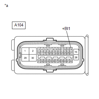
(b) Make sure that there is no looseness at the locking part and the connecting part of the connector.
OK:
The connector is securely connected.
(c) Disconnect the A104 No. 1 skid control ECU (brake booster with master cylinder assembly) connector.
(d) Check both the connector case and the terminals for deformation and corrosion.
OK:
No deformation or corrosion.
(e) Measure the voltage according to the value(s) in the table below.
Standard Voltage:
|
Tester Connection |
Condition |
Specified Condition |
|---|---|---|
|
A104-14 (+BI1) - Body ground |
Always |
11 to 14 V |
| NG |
|
REPAIR OR REPLACE HARNESS OR CONNECTOR |
|
|
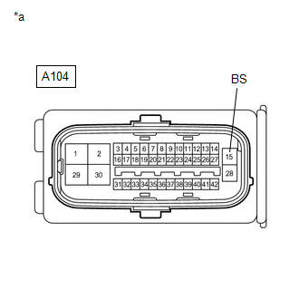
5. |
CHECK HARNESS AND CONNECTOR (BS TERMINAL) |
|
(a) Measure the voltage according to the value(s) in the table below. Standard Voltage:
|
|
| OK |
|
REPLACE BRAKE BOOSTER WITH MASTER CYLINDER ASSEMBLY
|
| NG |
|
REPAIR OR REPLACE HARNESS OR CONNECTOR |
|
|
|