| Last Modified: 01-30-2024 | 6.11:8.1.0 | Doc ID: RM10000000214Q6 |
| Model Year Start: 2022 | Model: RAV4 | Prod Date Range: [12/2021 - 10/2023] |
| Title: BRAKE CONTROL / DYNAMIC CONTROL SYSTEMS: ELECTRONICALLY CONTROLLED BRAKE SYSTEM (w/o Vacuum Brake Booster): C125609; Accumulator Low Pressure Abnormality Component Failure; 2022 - 2023 MY RAV4 RAV4 HV [12/2021 - 10/2023] | ||
|
DTC |
C125609 |
Accumulator Low Pressure Abnormality Component Failure |
DESCRIPTION
The accumulator pressure sensor is built into the brake booster with master cylinder assembly and detects the accumulator pressure.
The No. 1 skid control ECU (brake booster with master cylinder assembly) turns on the brake system warning light (red indicator) and brake system warning light (yellow indicator), and sounds the meter buzzer if it senses a decrease in the accumulator pressure.
DTC C125609 may be stored if the accumulator pressure drops due to frequent braking (this is not a malfunction).
|
DTC No. |
Detection Item |
DTC Detection Condition |
Trouble Area |
MIL |
Note |
|---|---|---|---|---|---|
|
C125609 |
Accumulator Low Pressure Abnormality Component Failure |
When the vehicle speed is 3 km/h (2 mph) or more, the accumulator pressure is excessively low. (DTCs will be stored and the buzzer will sound when the above condition is met.) |
|
Comes on |
|
MONITOR DESCRIPTION
The No. 2 skid control ECU (brake actuator assembly) monitors the value of the accumulator pressure using the accumulator pressure sensor.
If any of the following conditions are met for a certain amount of time, the No. 2 skid control ECU (brake actuator assembly) judges that the accumulator pressure is low and illuminates the MIL and stores this DTC.
- The accumulator pressure does not increase when the pump motor is operated.
- The accumulator pressure is not a specific value or more after starting the No. 2 skid control ECU (brake actuator assembly).
- The accumulator pressure is less than a specific value.
MONITOR STRATEGY
|
Related DTCs |
C1256: Brake booster motor pressure too low |
|
Required Sensors/Components(Main) |
Brake booster with accumulator pump assembly Brake actuator (brake booster with master cylinder assembly) |
|
Required Sensors/Components(Related) |
No. 2 skid control ECU (brake actuator assembly) Brake actuator (brake booster with master cylinder assembly) Stop light switch assembly |
|
Frequency of Operation |
Continuous |
|
Duration |
1.698 to 9 seconds (Time depends on auxiliary battery voltage): C1256 (Case 1-1) 3 seconds: C1256 (Case 1-2) 33 to 99 seconds (Time depends on auxiliary battery voltage): C1256 (Case 1-3) |
|
MIL Operation |
Immediately |
|
Sequence of Operation |
None |
TYPICAL ENABLING CONDITIONS
All
|
Monitor runs whenever the following DTCs are not stored |
C0573 (Case 1): Accumulator pressure sensor lost communication C0573 (Case 2): Accumulator pressure sensor internal malfunction C0573 (Case 3): Accumulator pressure sensor invalid data C149E: Accumulator pressure sensor voltage circuit low C149F: Accumulator pressure sensor voltage circuit high C14D3: Accumulator pressure sensor intermittent/erratic |
Case 1-1
|
All of the following conditions are met |
- |
|
Brake booster pressure sensor fail |
Not detected |
|
Brake booster pressure |
Less than 16.2 Mpa (165.2 kgf/cm2, 2349 psi) |
|
Brake |
Off |
|
Brake system voltage 1 (VM1) |
Higher than 7.3 V |
|
Servo pressure sensor fail |
Not detected |
Case 1-2
|
All of the following conditions are met |
- |
|
Brake booster pressure sensor fail |
Not detected |
|
Brake booster pressure |
Less than 16.2 Mpa (165.2 kgf/cm2, 2349 psi) |
|
Brake booster motor control circuit high |
Not detected |
|
Brake |
Off |
|
Brake system voltage 1 (VM1) |
Higher than 7.3 V |
|
Servo pressure sensor fail |
Not detected |
Case 1-3
|
Both of the following conditions are met |
- |
|
Brake booster pressure sensor fail |
Not detected |
|
Brake booster pressure |
Less than 16.2 Mpa (165.2 kgf/cm2, 2349 psi) |
TYPICAL MALFUNCTION THRESHOLDS
Case 1-1
|
Brake booster pressure increase when brake booster motor is operating |
Less than 0.25 MPa (2.5 kgf/cm2, 36 psi) |
Case 1-2
|
Brake booster pressure after ECU power on |
Less than 6 MPa (61.2 kgf/cm2, 870 psi) |
Case 1-3
|
Brake booster pressure |
Less than 14 MPa (142.8 kgf/cm2, 2031 psi) |
COMPONENT OPERATING RANGE
All
|
Both of the following conditions are met |
- |
|
Brake booster pressure sensor fail |
Not detected |
|
Brake booster pressure |
15 MPa (153.0 kgf/cm2, 2175 psi) or more |
CONFIRMATION DRIVING PATTERN
NOTICE:
When performing the normal judgment procedure, make sure that the driver door is closed and is not opened at any time during the procedure.
HINT:
- After repair has been completed, clear the DTC and then check that the vehicle has returned to normal by performing the following All Readiness check procedure.
- When clearing the permanent DTCs, refer to the "CLEAR PERMANENT DTC" procedure.
- Connect the GTS to the DLC3.
- Turn the ignition switch to ON and turn the GTS on.
- Clear the DTCs (even if no DTCs are stored, perform the clear DTC procedure).
- Turn the ignition switch off.
- Turn the ignition switch to ON (READY) and turn the GTS on.
-
Repeat the following step 10 times. [*1]
- Fully depress the brake pedal for 2 seconds, release it and wait 1 second.
-
Wait 100 seconds. [*2]
HINT:
[*1] to [*2]: Normal judgment procedure.
The normal judgment procedure is used to complete DTC judgment and also used when clearing permanent DTCs.
- Enter the following menus: Chassis / Brake/EPB / Utility / All Readiness.
-
Check the DTC judgment result.
HINT:
- If the judgment result shows NORMAL, the system is normal.
- If the judgment result shows ABNORMAL, the system has a malfunction.
- If the judgment result shows INCOMPLETE, perform driving pattern again.
WIRING DIAGRAM
Refer to DTC C059400.
Click here
![2022 - 2023 MY RAV4 RAV4 HV [12/2021 - 10/2023]; BRAKE CONTROL / DYNAMIC CONTROL SYSTEMS: ELECTRONICALLY CONTROLLED BRAKE SYSTEM (w/o Vacuum Brake Booster): C059400; Brake Booster Motor "A" Performance](/t3Portal/stylegraphics/info.gif)
CAUTION / NOTICE / HINT
NOTICE:
- Inspect the fuses for circuits related to this system before performing the following procedure.
-
After replacing the No. 1 skid control ECU (brake booster with master cylinder assembly), perform "Calibration" after performing "Reset Memory".
Click here
PROCEDURE
|
1. |
CHECK DTC |
(a) Check the DTCs that are output.
Chassis > Brake Booster > Trouble Codes
Chassis > Brake/EPB > Trouble Codes
|
Result |
Proceed to |
|---|---|
|
Only DTC C125609 is output. |
A |
|
DTCs other than C125609 are output. |
B |
| B |

|
REPAIR CIRCUITS INDICATED BY OUTPUT DTCS |
|

|
2. |
INSPECT BRAKE BOOSTER WITH ACCUMULATOR PUMP ASSEMBLY |
|
(a) Turn the ignition switch off. |
|
(b) Make sure that there is no looseness at the locking part and the connecting part of the connector.
OK:
The connector is securely connected.
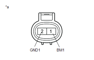
(c) Disconnect the A106 brake booster with accumulator pump assembly connector.
(d) Check both the connector case and the terminals for deformation and corrosion.
OK:
No deformation or corrosion.
(e) Measure the resistance according to the value(s) in the table below.
Standard Resistance:
|
Tester Connection |
Condition |
Specified Condition |
|---|---|---|
|
1 (BM1) - 2 (GND1) |
Always |
10 Ω or less |
| NG |
|
REPLACE BRAKE BOOSTER WITH ACCUMULATOR PUMP ASSEMBLY
|
|
|
3. |
READ VALUE USING GTS (ACCUMULATOR PRESSURE) |
(a) Reconnect the A106 brake booster with accumulator pump assembly connector.
(b) Disconnect the A103 brake pedal stroke sensor assembly connector.
(c) Depress the brake pedal several times to operate the pump motor, then wait until it stops.
(d) After the pump motor stops, wait for 30 seconds, then check the drop in the accumulator pressure sensor output value and the state of the pump motor.
Chassis > Brake Booster > Data List
|
Tester Display |
Measurement Item |
Range |
Normal Condition |
Diagnostic Note |
|---|---|---|---|---|
|
ECB Motor Relay |
Motor relay operation request |
OFF / ON |
OFF: Relay off ON: Relay on |
ECB: Electronically Controlled Brake System |
|
Accumulator Pressure |
Accumulator pressure output value |
Min.: 0.00 MPa Max.: 24.48 MPa |
15.00 to 21.00 MPa (Pressure stable and pump motor stopped) |
When brake fluid is stored in the accumulator: Accumulator pressure changes in accordance with volume of fluid stored in the accumulator |
Chassis > Brake Booster > Data List
|
Tester Display |
|---|
|
ECB Motor Relay |
|
Accumulator Pressure |
|
Result |
Proceed to |
|---|---|
|
The drop in the accumulator pressure sensor output value is less than 2.50 MPa 30 seconds after the pump motor stops, and the pump motor does not operate within 30 seconds after the pump motor stops. |
A |
|
The drop in the accumulator pressure sensor output value is 2.50 MPa or more 30 seconds after the pump motor stops, or the pump motor operates within 30 seconds after the pump motor stops. |
B |
| A |
|
|
|
4. |
READ VALUE USING GTS (SERVO PRESSURE) |
(a) Turn the ignition switch off.
(b) Reconnect the A103 brake pedal stroke sensor assembly connector.
(c) Perform the Active Test and operate the linear solenoid (SLR) in the brake booster with master cylinder assembly.
(d) Check that the servo pressure output value does not increase when performing the Active Test.
Chassis > Brake Booster > Active Test
|
Tester Display |
Measurement Item |
Control Range |
Restrict Condition |
Diagnostic Note |
|---|---|---|---|---|
|
ECB Solenoid (SLR) |
Linear solenoid reduction valve (SLR) |
Solenoid Start (Activate) Solenoid SLR (It is possible to set the current) |
Vehicle condition:
|
ECB: Electronically Controlled Brake System |
Chassis > Brake Booster > Data List
|
Tester Display |
Measurement Item |
Range |
Normal Condition |
Diagnostic Note |
|---|---|---|---|---|
|
Servo Pressure |
Pressure value of servo |
Min.: 0.00 MPa Max.: 24.48 MPa |
Brake pedal released: 0.00 to 1.53 MPa |
Brake pedal is being depressed: Changes in proportion to the depression force of the brake pedal |
Chassis > Brake Booster > Active Test
|
Active Test Display |
|---|
|
ECB Solenoid (SLR) |
|
Data List Display |
|---|
|
Servo Pressure |
OK:
The servo pressure output value does not increase when performing the Active Test.
HINT:
- If the servo pressure output value increases, an internal brake fluid leak in the brake booster with master cylinder assembly is suspected.
- Perform the Active Test with the current set to maximum.
|
Result |
Proceed to |
|---|---|
|
The servo pressure output value increases. |
A |
|
The servo pressure output value does not increase. |
B |
| A |
|
REPLACE BRAKE BOOSTER WITH MASTER CYLINDER ASSEMBLY
|
| B |
|
REPLACE BRAKE BOOSTER WITH MASTER CYLINDER ASSEMBLY AND BRAKE BOOSTER WITH ACCUMULATOR PUMP ASSEMBLY for Brake Booster with Master Cylinder Assembly: Click here
for Brake Booster with Accumulator Pump Assembly: Click here
|
|
|
|