| Last Modified: 01-30-2024 | 6.11:8.1.0 | Doc ID: RM10000000214Q0 |
| Model Year Start: 2022 | Model: RAV4 | Prod Date Range: [12/2021 - 10/2023] |
| Title: BRAKE CONTROL / DYNAMIC CONTROL SYSTEMS: ELECTRONICALLY CONTROLLED BRAKE SYSTEM (w/o Vacuum Brake Booster): C120200; Master Reservoir Level Malfunction; 2022 - 2023 MY RAV4 RAV4 HV [12/2021 - 10/2023] | ||
|
DTC |
C120200 |
Master Reservoir Level Malfunction |
DESCRIPTION
|
DTC No. |
Detection Item |
DTC Detection Condition |
Trouble Area |
MIL |
Note |
|---|---|---|---|---|---|
|
C120200 |
Master Reservoir Level Malfunction |
Either of the following is detected:
|
|
Comes on |
HINT: DTC C120200 is cleared when the conditions return to normal. |
C120200 DTC Detection Conditions
|
Vehicle Condition |
|||
|---|---|---|---|
|
Pattern 1 |
Pattern 2 |
||
|
Diagnosis Condition |
- |
- |
- |
|
Malfunction Status |
The brake fluid level warning switch signal circuit is open for a certain period of time |
○ |
- |
|
The reservoir level is low for a certain period of time |
- |
○ |
|
|
Detection Time |
- |
- |
|
|
Number of Trips |
1 trip |
1 trip |
|
HINT:
DTC will be output when conditions for either of the patterns in the table above are met.
MONITOR DESCRIPTION
When the ignition switch is turned to ON and the fluid level warning switch (brake booster with master cylinder assembly) is on for a certain amount of time, the No. 2 skid control ECU (brake actuator assembly) judges that the brake fluid level in the reservoir is low and illuminates the MIL and stores this DTC.
MONITOR STRATEGY
|
Related DTCs |
C1202: Reservoir level too low |
|
Required Sensors/Components(Main) |
Brake fluid level warning switch (brake booster with master cylinder assembly) No. 2 skid control ECU (brake actuator assembly) |
|
Required Sensors/Components(Related) |
No. 2 skid control ECU (brake actuator assembly) |
|
Frequency of Operation |
Continuous |
|
Duration |
20 seconds |
|
MIL Operation |
Immediately |
|
Sequence of Operation |
None |
TYPICAL ENABLING CONDITIONS
|
Monitor runs whenever the following DTCs are not stored |
C123B: Brake system voltage input open circuit U025E: Lost communication with electronic brake booster control unit (C-bus) |
|
Ignition switch |
On |
TYPICAL MALFUNCTION THRESHOLDS
|
Either of the following conditions is met |
- |
|
Reservoir level switch state |
On |
|
Serial communication with IC |
Invalid |
COMPONENT OPERATING RANGE
|
All of the following conditions are met |
- |
|
Serial communication with IC |
Valid |
|
Ignition switch |
On |
|
Reservoir level switch state |
Off |
CONFIRMATION DRIVING PATTERN
NOTICE:
When performing the normal judgment procedure, make sure that the driver door is closed and is not opened at any time during the procedure.
HINT:
- After repair has been completed, clear the DTC and then check that the vehicle has returned to normal by performing the following All Readiness check procedure.
- When clearing the permanent DTCs, refer to the "CLEAR PERMANENT DTC" procedure.
- Connect the GTS to the DLC3.
- Turn the ignition switch to ON and turn the GTS on.
- Clear the DTCs (even if no DTCs are stored, perform the clear DTC procedure).
- Turn the ignition switch off.
- Turn the ignition switch to ON (READY) and turn the GTS on.
-
Wait 20 seconds. [*]
HINT:
[*]: Normal judgment procedure.
The normal judgment procedure is used to complete DTC judgment and also used when clearing permanent DTCs.
- Enter the following menus: Chassis / Brake/EPB / Utility / All Readiness.
-
Check the DTC judgment result.
HINT:
- If the judgment result shows NORMAL, the system is normal.
- If the judgment result shows ABNORMAL, the system has a malfunction.
- If the judgment result shows INCOMPLETE, perform driving pattern again.
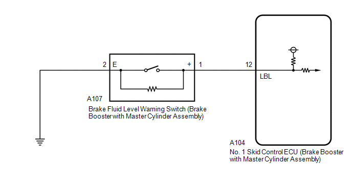
WIRING DIAGRAM
CAUTION / NOTICE / HINT
NOTICE:
After replacing the No. 1 skid control ECU (brake booster with master cylinder assembly), perform "Calibration" after performing "Reset Memory".
Click here
![2022 - 2024 MY RAV4 RAV4 HV [12/2021 - ]; BRAKE CONTROL / DYNAMIC CONTROL SYSTEMS: ELECTRONICALLY CONTROLLED BRAKE SYSTEM (w/o Vacuum Brake Booster): UTILITY](/t3Portal/stylegraphics/info.gif)
PROCEDURE
|
1. |
CHECK DTC |
(a) Check the DTCs that are output.
Chassis > Brake Booster > Trouble Codes
Chassis > Brake/EPB > Trouble Codes
|
Result |
Proceed to |
|---|---|
|
Only DTC C120200 is output. |
A |
|
DTCs other than C120200 are output. |
B |
| B |

|
REPAIR CIRCUITS INDICATED BY OUTPUT DTCS |
|

|
2. |
CHECK BRAKE FLUID LEVEL |
(a) Check that the brake fluid level is sufficient.
HINT:
If the fluid level is low, check for fluid leaks, and repair as necessary.
(1) Check for brake fluid leaks (connection between the brake booster with accumulator pump assembly, brake fluid level warning switch (brake booster with master cylinder assembly), brake booster with master cylinder assembly, and wheel cylinders).
HINT:
If no leaks exist, add and adjust fluid using the GTS.
Click here
(2) Check the thickness of the brake pad lining.
for Front Brake: Click here
for Rear Brake: Click here
HINT:
If the thickness is less than the standard, replace the brake pads with new ones.
(b) Check that there are no leaks from the connections between the brake booster with accumulator pump assembly and brake booster with master cylinder assembly.
HINT:
As a visual check is very difficult, perform the check with the following procedure.
(1) Bleed the air from the brake system.
Click here
(2) Turn the ignition switch off.
(3) Disconnect the A103 brake pedal stroke sensor assembly connector.
(4) Depress the brake pedal several times to operate the pump motor, then wait until it stops.
(5) After the pump motor stops, wait for 30 seconds, then check the drop in the accumulator pressure sensor output value and the state of the pump motor.
Chassis > Brake Booster > Data List
|
Tester Display |
Measurement Item |
Range |
Normal Condition |
Diagnostic Note |
|---|---|---|---|---|
|
ECB Motor Relay |
Motor relay operation request |
OFF / ON |
OFF: Relay off ON: Relay on |
ECB: Electronically Controlled Brake System |
|
Accumulator Pressure |
Accumulator pressure output value |
Min.: 0.00 MPa Max.: 24.48 MPa |
15.00 to 21.00 MPa (Pressure stable and pump motor stopped) |
When brake fluid is stored in the accumulator: Accumulator pressure changes in accordance with volume of fluid stored in the accumulator |
Chassis > Brake Booster > Data List
|
Tester Display |
|---|
|
ECB Motor Relay |
|
Accumulator Pressure |
|
Result |
Proceed to |
|---|---|
|
The drop in the accumulator pressure sensor output value is less than 2.50 MPa 30 seconds after the pump motor stops, and the pump motor does not operate within 30 seconds after the pump motor stops. |
A |
|
The drop in the accumulator pressure sensor output value is 2.50 MPa or more 30 seconds after the pump motor stops, or the pump motor operates within 30 seconds after the pump motor stops. |
B |
| B |
|
CHECK AND REPAIR BRAKE FLUID LEAKS OR ADD FLUID |
|
|
3. |
INSPECT BRAKE BOOSTER WITH MASTER CYLINDER ASSEMBLY |
|
(a) Turn the ignition switch off. |
|
(b) Reconnect the A103 brake pedal stroke sensor assembly connector.
(c) Remove the brake master cylinder reservoir filler cap assembly.
(d) Make sure that there is no looseness at the locking part and the connecting part of the connector.
OK:
The connector is securely connected.
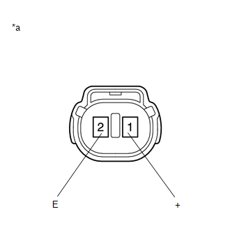
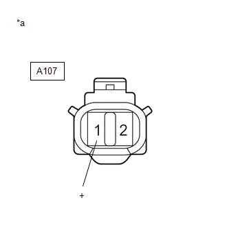
(e) Disconnect the A107 brake fluid level warning switch (brake booster with master cylinder assembly) connector.
(f) Check both the connector case and the terminals for deformation and corrosion.
OK:
No deformation or corrosion.
(g) Measure the resistance according to the value(s) in the table below.
HINT:
A float is located inside the brake fluid level warning switch (brake booster with master cylinder assembly). Its position changes according to the level of brake fluid.
Standard Resistance:
|
Tester Connection |
Condition |
Specified Condition |
|---|---|---|
|
1 (+) - 2 (E) |
Brake fluid level warning switch (brake booster with master cylinder assembly) off (float up) |
1.84 to 2.16 kΩ |
|
1 (+) - 2 (E) |
Brake fluid level warning switch (brake booster with master cylinder assembly) on (float down) |
Below 1 Ω (Brake fluid level is low) |
(h) If there are no problems after completing the preceding inspection, adjust the brake fluid to the MAX level with the ignition switch turned to ON.
| NG |
|
REPLACE BRAKE BOOSTER WITH MASTER CYLINDER ASSEMBLY |
|
|
4. |
CHECK HARNESS AND CONNECTOR (BRAKE BOOSTER WITH MASTER CYLINDER ASSEMBLY - BRAKE FLUID LEVEL WARNING SWITCH) |
(a) Turn the ignition switch off.
(b) Make sure that there is no looseness at the locking part and the connecting part of the connector.
OK:
The connector is securely connected.
(c) Disconnect the A104 No. 1 skid control ECU (brake booster with master cylinder assembly) connector.
(d) Check both the connector case and the terminals for deformation and corrosion.
OK:
No deformation or corrosion.
(e) Measure the resistance according to the value(s) in the table below.
Standard Resistance:
|
Tester Connection |
Condition |
Specified Condition |
|---|---|---|
|
A104-12 (LBL) - A107-1 (+) |
Always |
Below 1 Ω |
|
A104-12 (LBL) or A107-1 (+) - Body ground |
Always |
10 kΩ or higher |
|
A107-2 (E) - Body ground |
1 minute or more after disconnecting the cable from the negative (-) auxiliary battery terminal |
Below 1 Ω |
| NG |
|
REPAIR OR REPLACE HARNESS OR CONNECTOR |
|
|
5. |
INSPECT BRAKE BOOSTER WITH MASTER CYLINDER ASSEMBLY (SWITCH INPUT) |
|
(a) Reconnect the A104 No. 1 skid control ECU (brake booster with master cylinder assembly) connector. |
|
(b) Turn the ignition switch to ON.
(c) Measure the voltage according to the value(s) in the table below.
Standard Voltage:
|
Tester Connection |
Condition |
Specified Condition |
|---|---|---|
|
A107-1 (+) - Body ground |
Ignition switch ON |
11 to 14 V |
| NG |
|
REPLACE BRAKE BOOSTER WITH MASTER CYLINDER ASSEMBLY
|
|
|
6. |
CLEAR DTC |
(a) Turn the ignition switch off.
(b) Reconnect the A107 brake fluid level warning switch (brake booster with master cylinder assembly) connector.
(c) Clear the DTCs.
Chassis > Brake Booster > Clear DTCs
(d) Turn the ignition switch off.
|
|
7. |
RECONFIRM DTC |
(a) Based on the Freeze Frame Data and interview with the customer, attempt to reproduce the conditions when the malfunction occurred.
(b) Check if the same DTC is output.
Chassis > Brake Booster > Trouble Codes
|
Result |
Proceed to |
|---|---|
|
DTC C120200 is not output. |
A |
|
DTC C120200 is output. |
B |
| A |
|
| B |
|
REPLACE BRAKE BOOSTER WITH MASTER CYLINDER ASSEMBLY
|
|
|
|