| Last Modified: 01-30-2024 | 6.11:8.1.0 | Doc ID: RM10000000214PZ |
| Model Year Start: 2022 | Model: RAV4 | Prod Date Range: [12/2021 - ] |
| Title: BRAKE CONTROL / DYNAMIC CONTROL SYSTEMS: ELECTRONICALLY CONTROLLED BRAKE SYSTEM (w/o Vacuum Brake Booster): C110E14; Brake Booster Motor "A" Supply Voltage Circuit Short to Ground or Open; 2022 - 2024 MY RAV4 RAV4 HV [12/2021 - ] | ||
|
DTC |
C110E14 |
Brake Booster Motor "A" Supply Voltage Circuit Short to Ground or Open |
DESCRIPTION
If a malfunction is detected in the power supply circuit, the No. 1 skid control ECU (brake booster with master cylinder assembly) power source voltage drops, or there is insufficient voltage to operate the main relay, the No. 2 skid control ECU (brake actuator assembly) will store these DTCs.
If the auxiliary battery voltage is temporarily low, these DTCs may be stored.
HINT:
DTCs C125600 or C125609 may also be memorized if there is a drop in power source voltage.
|
DTC No. |
Detection Item |
DTC Detection Condition |
Trouble Area |
MIL |
Note |
|---|---|---|---|---|---|
|
C110E14 |
Brake Booster Motor "A" Supply Voltage Circuit Short to Ground or Open |
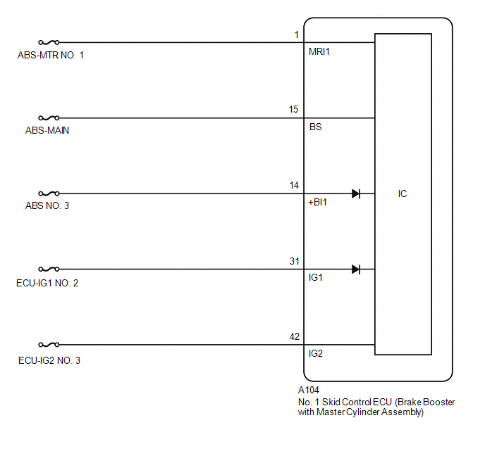
When the voltage at terminal +BI1 is more than 7.3 V, the voltage at terminal MRI1 is less than 5.7 V for 1 second or more. |
|
Comes on |
|
MONITOR DESCRIPTION
When the voltage at MRI1 drops due to a malfunction in the auxiliary battery and hybrid control system (charging circuit), the No. 2 skid control ECU (brake actuator assembly) judges that there is a drop in the power supply and illuminates the MIL and stores a DTC.
MONITOR STRATEGY
|
Related DTCs |
C110F: Brake system voltage circuit low |
|
Required Sensors/Components(Main) |
No. 2 skid control ECU (brake actuator assembly) |
|
Required Sensors/Components(Related) |
No. 2 skid control ECU (brake actuator assembly) |
|
Frequency of Operation |
Continuous |
|
Duration |
1 second: C110F (Case 1) 1.002 seconds: C110F (Case 2) |
|
MIL Operation |
Immediately |
|
Sequence of Operation |
None |
TYPICAL ENABLING CONDITIONS
All
|
Monitor runs whenever the following DTCs are not stored |
C14C7 (Case 3 to 9): Brake system voltage circuit low |
Case 1
|
Brake system voltage 1 |
Higher than 7.3 V |
Case 2
|
All of the following conditions are met |
- |
|
Brake system voltage 1 |
Higher than 7.3 V |
|
Motor relay input signal permission |
Off |
|
Command to motor relay |
Off |
|
Motor duty output order value |
0% |
TYPICAL MALFUNCTION THRESHOLDS
All
|
MRI1 voltage |
Less than 5.7 V |
COMPONENT OPERATING RANGE
C110F (Case 1)
|
All of the following conditions are met |
A, B, C and D |
|
A. Brake system voltage 1 |
Higher than 7.3 V |
|
B. MRI1 voltage |
5.7 V or more |
|
C. All of the following conditions are met at the ECU status (last IG ON timing final) |
- |
|
Brake system voltage fail (C12FA, C12FB) |
Not detected |
|
Brake booster motor fail (C141C, C141D, C141E, C141F) |
Not detected |
|
Brake pressure control solenoid fail (C14F4, C14FD, C150A, C1510) |
Not detected |
|
D. All of the following conditions are met at the ECU status (pre main) |
- |
|
Brake system voltage fail (C121F, C12FA, C12FB) |
Not detected |
|
Brake booster motor fail (C141C) |
Not detected |
|
Brake pressure control solenoid fail (C14F3, C14F4, C14FC, C14FD, C1509, C150A, C150F, C1510) |
Not detected |
C110F (Case 2)
|
All of the following conditions are met |
A, B, C, D, E, F and G |
|
A. Brake system voltage 1 |
Higher than 7.3 V |
|
B. Motor relay input signal permission |
Off |
|
C. Command to motor relay |
Off |
|
D. Motor duty output order value |
0% |
|
E. MRI1 voltage |
5.7 V or more |
|
F. All of the following conditions are met at the ECU status (last IG ON timing final) |
- |
|
Brake system voltage fail (C12FA, C12FB) |
Not detected |
|
Brake booster motor fail (C141C, C141D, C141E, C141F) |
Not detected |
|
Brake pressure control solenoid fail (C14F4, C14FD, C150A, C1510) |
Not detected |
|
G. All of the following conditions are met at the ECU status (pre main) |
- |
|
Brake system voltage fail (C121F, C12FA, C12FB) |
Not detected |
|
Brake booster motor fail (C141C) |
Not detected |
|
Brake pressure control solenoid fail (C14F3, C14F4, C14FC, C14FD, C1509, C150A, C150F, C1510) |
Not detected |
CONFIRMATION DRIVING PATTERN
NOTICE:
When performing the normal judgment procedure, make sure that the driver door is closed and is not opened at any time during the procedure.
HINT:
- After repair has been completed, clear the DTC and then check that the vehicle has returned to normal by performing the following All Readiness check procedure.
- When clearing the permanent DTCs, refer to the "CLEAR PERMANENT DTC" procedure.
- Connect the GTS to the DLC3.
- Turn the ignition switch to ON and turn the GTS on.
- Clear the DTCs (even if no DTCs are stored, perform the clear DTC procedure).
- Turn the ignition switch off.
- Turn the ignition switch to ON (READY) and turn the GTS on.
-
Wait for 2 seconds or more. [*]
HINT:
[*]: Normal judgment procedure.
The normal judgment procedure is used to complete DTC judgment and also used when clearing permanent DTCs.
- Enter the following menus: Chassis / Brake/EPB / Utility / All Readiness.
-
Check the DTC judgment result.
HINT:
- If the judgment result shows NORMAL, the system is normal.
- If the judgment result shows ABNORMAL, the system has a malfunction.
- If the judgment result shows INCOMPLETE, perform driving pattern again.
WIRING DIAGRAM
CAUTION / NOTICE / HINT
NOTICE:
- Inspect the fuses for circuits related to this system before performing the following procedure.
-
Before performing troubleshooting, make sure to confirm that the auxiliary battery voltage is normal.
Click here
![2019 - 2024 MY RAV4 RAV4 HV [11/2018 - ]; INTRODUCTION: HOW TO TROUBLESHOOT ECU CONTROLLED SYSTEMS: HOW TO PROCEED WITH TROUBLESHOOTING](/t3Portal/stylegraphics/info.gif)
-
After replacing the No. 1 skid control ECU (brake booster with master cylinder assembly), perform "Calibration" after performing "Reset Memory".
Click here
PROCEDURE
|
1. |
CHECK DTC |
(a) Check the DTCs that are output.
Chassis > Brake Booster > Trouble Codes
Chassis > Brake/EPB > Trouble Codes
|
Result |
Proceed to |
|---|---|
|
Only DTC C110E14 is output. |
A |
|
DTCs other than C110E14 are output. |
B |
| B |

|
REPAIR CIRCUITS INDICATED BY OUTPUT DTCS |
|

|
2. |
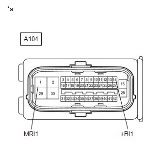
CHECK HARNESS AND CONNECTOR (+BI1 AND MRI1 TERMINAL) |
|
(a) Turn the ignition switch off. |
|
(b) Make sure that there is no looseness at the locking part and the connecting part of the connector.
OK:
The connector is securely connected.
(c) Disconnect the A104 No. 1 skid control ECU (brake booster with master cylinder assembly) connector.
(d) Check both the connector case and the terminals for deformation and corrosion.
OK:
No deformation or corrosion.
(e) Measure the voltage according to the value(s) in the table below.
Standard Voltage:
|
Tester Connection |
Condition |
Specified Condition |
|---|---|---|
|
A104-14 (+BI1) - Body ground |
Always |
11 to 14 V |
|
A104-1 (MRI1) - Body ground |
Always |
11 to 14 V |
|
Result |
Proceed to |
|---|---|
|
11 to 14 V. |
A |
|
Below 11 V. |
B |
| A |
|
REPLACE BRAKE BOOSTER WITH MASTER CYLINDER ASSEMBLY
|
| B |
|
REPAIR OR REPLACE HARNESS OR CONNECTOR |
|
|
|