| Last Modified: 01-30-2024 | 6.11:8.1.0 | Doc ID: RM10000000214PR |
| Model Year Start: 2022 | Model: RAV4 | Prod Date Range: [12/2021 - 10/2023] |
| Title: BRAKE CONTROL / DYNAMIC CONTROL SYSTEMS: ELECTRONICALLY CONTROLLED BRAKE SYSTEM (w/o Vacuum Brake Booster): C05C100; Brake Pedal Position Sensor "B"; 2022 - 2023 MY RAV4 RAV4 HV [12/2021 - 10/2023] | ||
|
DTC |
C05C100 |
Brake Pedal Position Sensor "B" |
DESCRIPTION
When the No. 2 skid control ECU (brake actuator assembly) judges that the zero point calibration of the brake pedal stroke sensor assembly is incomplete, this DTC is stored.
|
DTC No. |
Detection Item |
DTC Detection Condition |
Trouble Area |
MIL |
Note |
|---|---|---|---|---|---|
|
C05C100 |
Brake Pedal Position Sensor "B" |
When the vehicle speed is 40km/h (25 mph) or more, a valid brake pedal stroke sensor zero point is not memorized. |
|
Comes on |
HINT: During Dealer Mode, related DTCs are cleared (except SAE code). |
MONITOR DESCRIPTION
When any of the following operations are performed, the brake pedal stroke sensor assembly calibration is not performed, and the vehicle is driven at a certain speed or more, the No. 2 skid control ECU (brake actuator assembly) judges that calibration has not been performed, the MIL is illuminated and a DTC is stored.
- The No. 2 skid control ECU (brake actuator assembly) has been replaced with a new one.
- After the brake pedal stroke sensor assembly, brake pedal, brake booster with master cylinder assembly, brake actuator assembly or yaw rate and acceleration sensor (airbag ECU assembly) has been removed and installed or replaced, the zero point is cleared.
MONITOR STRATEGY
|
Related DTCs |
C05C1: Brake pedal position sensor learning not complete |
|
Required Sensors/Components(Main) |
No. 2 skid control ECU (brake actuator assembly) |
|
Required Sensors/Components(Related) |
Speed sensor |
|
Frequency of Operation |
Continuous |
|
Duration |
- |
|
MIL Operation |
Immediately |
|
Sequence of Operation |
None |
TYPICAL ENABLING CONDITIONS
|
Monitor runs whenever the following DTCs are not stored |
None |
|
Vehicle speed |
40 km/h (24.85 mph) or more |
TYPICAL MALFUNCTION THRESHOLDS
|
Either of the following conditions is met |
- |
|
Brake pedal position sensor 1: Zero position learning value |
Not stored |
|
Brake pedal position sensor 2: Zero position learning value |
Not stored |
COMPONENT OPERATING RANGE
|
Both of the following conditions are met |
- |
|
Brake pedal position sensor 1: Zero position learning value |
Stored |
|
Brake pedal position sensor 2: Zero position learning value |
Stored |
CONFIRMATION DRIVING PATTERN
NOTICE:
When performing the normal judgment procedure, make sure that the driver door is closed and is not opened at any time during the procedure.
HINT:
- After repair has been completed, clear the DTC and then check that the vehicle has returned to normal by performing the following All Readiness check procedure.
- When clearing the permanent DTCs, refer to the "CLEAR PERMANENT DTC" procedure.
- Connect the GTS to the DLC3.
- Turn the ignition switch to ON and turn the GTS on.
- Clear the DTCs (even if no DTCs are stored, perform the clear DTC procedure).
- Turn the ignition switch off.
- Turn the ignition switch to ON (READY) and turn the GTS on.
-
Drive the vehicle at a speed of 40 km/h (25 mph) or more for 1 minute. [*]
HINT:
[*]: Normal judgment procedure.
The normal judgment procedure is used to complete DTC judgment and also used when clearing permanent DTCs.
- Enter the following menus: Chassis / Brake/EPB / Utility / All Readiness.
-
Check the DTC judgment result.
HINT:
- If the judgment result shows NORMAL, the system is normal.
- If the judgment result shows ABNORMAL, the system has a malfunction.
- If the judgment result shows INCOMPLETE, perform driving pattern again.
WIRING DIAGRAM
Refer to DTC C110000.
Click here
![2022 - 2023 MY RAV4 RAV4 HV [12/2021 - 10/2023]; BRAKE CONTROL / DYNAMIC CONTROL SYSTEMS: ELECTRONICALLY CONTROLLED BRAKE SYSTEM (w/o Vacuum Brake Booster): C110000; Brake Pedal Position Sensor "A" Supply Voltage Malfunction](/t3Portal/stylegraphics/info.gif)
CAUTION / NOTICE / HINT
NOTICE:
After replacing or reinstalling the brake pedal stroke sensor assembly, perform "Calibration" after performing "Reset Memory".
Click here
PROCEDURE
|
1. |
PERFORM BRAKE PEDAL STROKE SENSOR ASSEMBLY ZERO POINT CALIBRATION |
(a) Perform brake pedal stroke sensor assembly zero point calibration.
Click here
Chassis > Brake/EPB > Utility
|
Tester Display |
|---|
|
Reset Memory |
Chassis > Brake/EPB > Utility
|
Tester Display |
|---|
|
Calibration |
|

|
2. |
CLEAR DTC |
(a) Clear the DTCs.
Chassis > Brake Booster > Clear DTCs
Chassis > Brake/EPB > Clear DTCs
(b) Turn the ignition switch off.
|
|
3. |
RECONFIRM DTC |
(a) Based on the Freeze Frame Data and interview with the customer, attempt to reproduce the conditions when the malfunction occurred.
(b) Check if the same DTC is output.
Chassis > Brake Booster > Trouble Codes
Chassis > Brake/EPB > Trouble Codes
|
Result |
Proceed to |
|---|---|
|
Only DTC C05C100 is output. |
A |
|
DTCs are not output. |
B |
|
DTCs other than C05C100 are output. |
C |
| B |

|
END |
| C |
|
REPAIR CIRCUITS INDICATED BY OUTPUT DTCS |
|
|
4. |
INSPECT BRAKE ACTUATOR ASSEMBLY (SENSOR OUTPUT) |
|
(a) Turn the ignition switch off. |
|
(b) Make sure that there is no looseness at the locking part and the connecting part of the connectors.
OK:
The connector is securely connected.
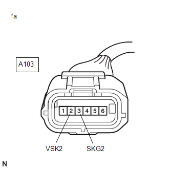
(c) Disconnect the A103 brake pedal stroke sensor assembly connector.
(d) Check both the connector case and the terminals for deformation and corrosion.
OK:
No deformation or corrosion.
(e) Turn the ignition switch to ON.
(f) Measure the voltage according to the value(s) in the table below.
Standard Voltage:
|
Tester Connection |
Condition |
Specified Condition |
|---|---|---|
|
A103-2 (VSK2) - A103-3 (SKG2) |
Ignition switch ON |
4.84 to 5.16 V |
| OK |
|
REPLACE BRAKE PEDAL STROKE SENSOR ASSEMBLY
|
| NG |
|
REPAIR OR REPLACE HARNESS OR CONNECTOR |
|
|
|