| Last Modified: 01-30-2024 | 6.11:8.1.0 | Doc ID: RM10000000214PG |
| Model Year Start: 2022 | Model: RAV4 | Prod Date Range: [12/2021 - ] |
| Title: BRAKE CONTROL / DYNAMIC CONTROL SYSTEMS: ELECTRONICALLY CONTROLLED BRAKE SYSTEM (w/o Vacuum Brake Booster): C052C14,...,C052F14; ABS Pump Motor Control Circuit Short to Ground or Open; 2022 - 2024 MY RAV4 RAV4 HV [12/2021 - ] | ||
|
DTC |
C052C14 |
ABS Pump Motor Control Circuit Short to Ground or Open |
|
DTC |
C052C16 |
ABS Pump Motor Control Circuit Voltage Below Threshold |
|
DTC |
C052C17 |
ABS Pump Motor Control Circuit Voltage Above Threshold |
|
DTC |
C052C49 |
ABS Pump Motor Control Internal Electronic Failure |
|
DTC |
C052F14 |
ABS Pump Motor Supply Voltage Circuit Short to Ground or Open |
DESCRIPTION
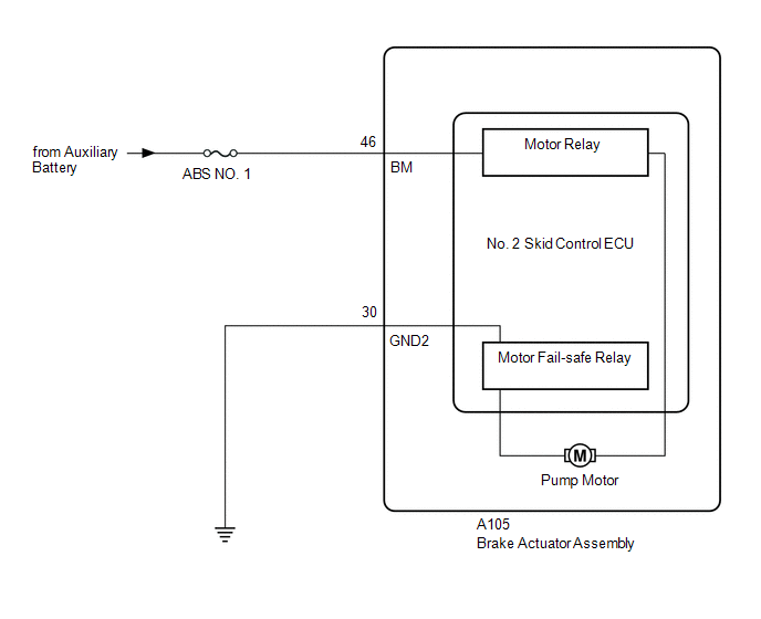
The motor relay and motor fail-safe relay are built into the brake actuator assembly.
When the No. 2 skid control ECU (brake actuator assembly) operates ABS, TRAC, VSC, or brake assist, etc., the motor relay turns ON and drives the pump motor built into the brake actuator assembly.
If any DTCs related to motor supply power are stored, fail-safe is performed and supply of power to the motor relay is cut by the motor fail-safe relay.
If the voltage supplied to the motor relay (BM terminal) is below the DTC detection threshold due to low voltage from the auxiliary battery or DC/DC converter circuit, these DTCs may be stored.
|
DTC No. |
Detection Item |
DTC Detection Condition |
Trouble Area |
MIL |
Note |
|---|---|---|---|---|---|
|
C052C14 |
ABS Pump Motor Control Circuit Short to Ground or Open |
When the voltage at terminal +BS is between 9.5 and 17.4 V and the motor is being driven at full power, an abnormal voltage is detected for 0.12 seconds or more. |
|
Comes on |
|
|
C052C16 |
ABS Pump Motor Control Circuit Voltage Below Threshold |
When the voltage at terminal +BS is between 9.5 and 17.4 V and the motor is stopped, the detected motor voltage is excessively low for 2 seconds or more. |
No. 2 skid control ECU (brake actuator assembly) |
Comes on |
|
|
C052C17 |
ABS Pump Motor Control Circuit Voltage Above Threshold |
When the voltage at terminal +BS is between 9.5 and 17.4 V and the motor is stopped, the detected motor voltage is excessively high for 2 seconds or more. |
No. 2 skid control ECU (brake actuator assembly) |
Comes on |
|
|
C052C49 |
ABS Pump Motor Control Internal Electronic Failure |
Either of the following is detected:
|
|
Comes on |
|
|
C052F14 |
ABS Pump Motor Supply Voltage Circuit Short to Ground or Open |
When voltage at +BS terminal is 9.5 V or more, open in BM terminal continues for 1 second or more. |
|
Comes on |
|
C052C49 DTC Detection Conditions
|
Vehicle Condition |
|||
|---|---|---|---|
|
Pattern 1 |
Pattern 2 |
||
|
Diagnosis Condition |
When the voltage at terminal +BS is between 9.5 and 17.4 V |
○ |
○ |
|
Malfunction Status |
Overcurrent is detected in the motor circuit |
○ |
- |
|
An abnormal voltage is detected in the motor relay gate |
- |
○ |
|
|
Detection Time |
0.05 seconds or more. |
0.12 seconds or more. |
|
|
Number of Trips |
1 trip |
1 trip |
|
HINT:
DTC will be output when conditions for either of the patterns in the table above are met.
MONITOR DESCRIPTION
C052B (Case 1):
- When the command to reverse battery protection MOS is ON and the reverse battery protection MOS gate voltage monitor is ON, the No. 2 skid control ECU (brake actuator assembly) judges that there is a malfunction, the MIL is illuminated and a DTC is stored .
C052B (Case 2):
- When the freewheeling MOS overcurrent signal is OFF and the motor relay gate voltage monitor is ON, the No. 2 skid control ECU (brake actuator assembly) judges that there is a malfunction, the MIL is illuminated and a DTC is stored.
C052B (Case 3 and 8):
-
When there is a command to turn off the motor relay, motor fail-safe relay, reverse battery protection MOS and freewheeling MOS, and any of the following conditions are met, the No. 2 skid control ECU (brake actuator assembly) judges that the gate voltage is abnormal, the MIL is illuminated and a DTC is stored.
- The motor relay gate voltage monitor is on.
- The reverse battery protection MOS gate voltage monitor is on.
- The freewheeling MOS gate voltage monitor is on.
C052B (Case 4, 6 and 9), C052D and C052E (Case 1 to 6):
- When the voltage upstream or downstream of the motor is outside of the specified range, the No. 2 skid control ECU (brake actuator assembly) judges that the gate voltage is abnormal or the motor circuit is malfunctioning, the MIL is illuminated and a DTC is stored.
C052B (Case 5):
- When there is a command to turn on the motor relay and the motor relay gate voltage monitor is off, the No. 2 skid control ECU (brake actuator assembly) judges that the gate voltage is abnormal, the MIL is illuminated and a DTC is stored.
C052B (Case 7):
- When there is a command to turn on the reverse battery protection MOS and the reverse battery protection MOS gate voltage monitor is off, the No. 2 skid control ECU (brake actuator assembly) judges that the gate voltage is abnormal, the MIL is illuminated and a DTC is stored.
C052B (Case 10):
- When this is no history of motor power supply voltage drop, there is a command to turn on the motor fail-safe relay, and overcurrent is detected in the motor circuit, the No. 2 skid control ECU (brake actuator assembly) judges that there is overcurrent, the MIL is illuminated and a DTC is stored.
C052B (Case 11):
- When the freewheeling MOS overcurrent signal is ON, the No. 2 skid control ECU (brake actuator assembly) judges that there is a malfunction, the MIL is illuminated and a DTC is stored.
C052E (Case 7):
- When there is a command to turn on the motor fail-safe relay and the freewheeling MOS, and the freewheeling MOS gate voltage monitor is off, the No. 2 skid control ECU (brake actuator assembly) judges that the relay is abnormal, the MIL is illuminated and a DTC is stored.
C055B:
- When the voltage at terminal +BM is less than a certain value, the No. 2 skid control ECU (brake actuator assembly) judges that the motor voltage is abnormal, the MIL is illuminated and a DTC is stored.
MONITOR STRATEGY
|
Related DTCs |
C052B: ABS pump motor performance C052D: ABS pump motor circuit high C052E: ABS pump motor open circuit C055B: ABS pump motor voltage circuit low |
|
Required Sensors/Components(Main) |
No. 2 skid control ECU (brake actuator assembly) |
|
Required Sensors/Components(Related) |
- |
|
Frequency of Operation |
Continuous |
|
Duration |
0.054 seconds: C052B (Case 10 and 11) 0.12 seconds: C052B (Case 1, 2, 4, 5, 7 and 8) and C052E (Case 3, 4, 5, 6 and 7) 1.002 seconds: C055B 2 seconds: C052D (Case 2) 2.004 seconds: C052E (Case 2) 4 seconds: C052D (Case 1) and C052E (Case 1) 4.002 seconds: C052B (Case 3, 6 and 9) and C052D (Case 3 and 4) |
|
MIL Operation |
Immediately |
|
Sequence of Operation |
None |
TYPICAL ENABLING CONDITIONS
C052B (Case 1)
|
Monitor runs whenever the following DTCs are not stored |
C052B (Case 2 to 11): ABS pump motor performance C052D: ABS pump motor circuit high C052E: ABS pump motor open circuit C055B: ABS pump motor voltage circuit low C0597 (Case 1): ABS hold solenoid circuit stuck C0597 (Case 2 to 5): ABS hold solenoid performance C12A7: ABS hold solenoid (FL) circuit low C12A8: ABS hold solenoid (FL) circuit high C12B2: ABS release solenoid (FL) circuit low C12B3: ABS release solenoid (FL) circuit high C12BD: ABS hold solenoid (FR) circuit low C12BE: ABS hold solenoid (FR) circuit high C12C8: ABS release solenoid (FR) circuit low C12C9: ABS release solenoid (FR) circuit high C12D3: ABS hold solenoid (RL) circuit low C12D4: ABS hold solenoid (RL) circuit high C12DE: ABS release solenoid (RL) circuit low C12DF: ABS release solenoid (RL) circuit high C12E9: ABS hold solenoid (RR) circuit low C12EA: ABS hold solenoid (RR) circuit high C12F4: ABS release solenoid (RR) circuit low C12F5: ABS release solenoid (RR) circuit high C12F6: ABS hold solenoid other functional C12F7: ABS hold solenoid other functional C137C: Brake system voltage input out of range low C137D: Brake system voltage input out of range high C13BF: SM solenoid other functional C13C2: SM1 solenoid circuit low C13C3: SM1 solenoid circuit high C13CB: SM2 solenoid circuit low C13CC: SM2 solenoid circuit high C1427: ABS pump motor stuck C143B: Brake system voltage solenoid relay stuck C143C: Brake system voltage open circuit |
|
All of the following conditions are met |
- |
|
+BS voltage |
9.5 V or more, and 17.4 V or less |
|
Command to reverse battery protection MOS |
On |
C052B (Case 2)
|
Monitor runs whenever the following DTCs are not stored |
C052B (Case 1, 3, 4 ,5, 6, 7, 8, 9, 10 and 11): ABS pump motor performance C052D: ABS pump motor circuit high C052E: ABS pump motor open circuit C055B: ABS pump motor voltage circuit low C0597 (Case 1): ABS hold solenoid circuit stuck C0597 (Case 2 to 5): ABS hold solenoid performance C12A7: ABS hold solenoid (FL) circuit low C12A8: ABS hold solenoid (FL) circuit high C12B2: ABS release solenoid (FL) circuit low C12B3: ABS release solenoid (FL) circuit high C12BD: ABS hold solenoid (FR) circuit low C12BE: ABS hold solenoid (FR) circuit high C12C8: ABS release solenoid (FR) circuit low C12C9: ABS release solenoid (FR) circuit high C12D3: ABS hold solenoid (RL) circuit low C12D4: ABS hold solenoid (RL) circuit high C12DE: ABS release solenoid (RL) circuit low C12DF: ABS release solenoid (RL) circuit high C12E9: ABS hold solenoid (RR) circuit low C12EA: ABS hold solenoid (RR) circuit high C12F4: ABS release solenoid (RR) circuit low C12F5: ABS release solenoid (RR) circuit high C12F6: ABS hold solenoid other functional C12F7: ABS hold solenoid other functional C137C: Brake system voltage input out of range low C137D: Brake system voltage input out of range high C13BF: SM solenoid other functional C13C2: SM1 solenoid circuit low C13C3: SM1 solenoid circuit high C13CB: SM2 solenoid circuit low C13CC: SM2 solenoid circuit high C1427: ABS pump motor stuck C143B: Brake system voltage solenoid relay stuck C143C: Brake system voltage open circuit |
|
All of the following conditions are met |
- |
|
+BS voltage |
9.5 V or more, and 17.4 V or less |
|
Motor circuit current |
Less than 264 A |
|
Freewheeling MOS overcurrent signal |
Off |
|
Motor duty output order value |
100% |
C052B (Case 3 and 8)
|
Monitor runs whenever the following DTCs are not stored |
C052B (Case 1, 2, 10 and 11): ABS pump motor performance C052D: ABS pump motor circuit high C052E: ABS pump motor open circuit C055B: ABS pump motor voltage circuit low C137C: Brake system voltage input out of range low C137D: Brake system voltage input out of range high |
|
All of the following conditions are met |
- |
|
+BS voltage |
9.5 V or more, and 17.4 V or less |
|
+BM voltage |
6 V or more |
|
Motor relay input signal permission |
Off |
|
Command to motor relay |
Off |
|
Motor duty output order value |
0% |
|
Command to reverse battery protection MOS |
Off |
|
Command to freewheeling MOS |
Off |
|
Command to motor fail-safe relay |
Off |
C052B (Case 4)
|
Monitor runs whenever the following DTCs are not stored |
C052B (Case 1, 2, 10 and 11): ABS pump motor performance C052D: ABS pump motor circuit high C052E: ABS pump motor open circuit C055B: ABS pump motor voltage circuit low C137C: Brake system voltage input out of range low C137D: Brake system voltage input out of range high |
|
All of the following conditions are met |
- |
|
+BS voltage |
9.5 V or more, and 17.4 V or less |
|
+BM voltage |
6 V or more |
|
Motor relay input signal permission |
On |
|
Command to motor relay |
Off |
|
Motor duty output order value |
0% |
|
Command to reverse battery protection MOS |
Off |
|
Command to freewheeling MOS |
On |
|
Command to motor fail-safe relay |
Off |
C052B (Case 5)
|
Monitor runs whenever the following DTCs are not stored |
C052B (Case 1, 2, 10 and 11): ABS pump motor performance C052D: ABS pump motor circuit high C052E: ABS pump motor open circuit C055B: ABS pump motor voltage circuit low C137C: Brake system voltage input out of range low C137D: Brake system voltage input out of range high |
|
All of the following conditions are met |
- |
|
+BS voltage |
9.5 V or more, and 17.4 V or less |
|
+BM voltage |
6 V or more |
|
Motor relay input signal permission |
On |
|
Command to motor relay |
On |
|
Motor duty output order value |
100% |
|
Command to reverse battery protection MOS |
Off |
|
Command to freewheeling MOS |
Off |
|
Command to motor fail-safe relay |
Off |
C052B (Case 6)
|
Monitor runs whenever the following DTCs are not stored |
C052B (Case 1, 2, 10 and 11): ABS pump motor performance C052D: ABS pump motor circuit high C052E: ABS pump motor open circuit C055B: ABS pump motor voltage circuit low C137C: Brake system voltage input out of range low C137D: Brake system voltage input out of range high |
|
All of the following conditions are met |
- |
|
+BS voltage |
9.5 V or more, and 17.4 V or less |
|
+BM voltage |
6 V or more |
|
Motor relay input signal permission |
Off |
|
Command to motor relay |
On |
|
Motor duty output order value |
100% |
|
Command to reverse battery protection MOS |
Off |
|
Command to freewheeling MOS |
Off |
|
Command to motor fail-safe relay |
Off |
C052B (Case 7)
|
Monitor runs whenever the following DTCs are not stored |
C052B (Case 1, 2, 10 and 11): ABS pump motor performance C052D: ABS pump motor circuit high C052E: ABS pump motor open circuit C055B: ABS pump motor voltage circuit low C137C: Brake system voltage input out of range low C137D: Brake system voltage input out of range high |
|
All of the following conditions are met |
- |
|
+BS voltage |
9.5 V or more, and 17.4 V or less |
|
+BM voltage |
6 V or more |
|
Motor relay input signal permission |
Off |
|
Command to motor relay |
Off |
|
Motor duty output order value |
0% |
|
Command to reverse battery protection MOS |
On |
|
Command to freewheeling MOS |
Off |
|
Command to motor fail-safe relay |
Off |
C052B (Case 9)
|
Monitor runs whenever the following DTCs are not stored |
C052B (Case 1, 2, 10 and 11): ABS pump motor performance C052D: ABS pump motor circuit high C052E: ABS pump motor open circuit C055B: ABS pump motor voltage circuit low C137C: Brake system voltage input out of range low C137D: Brake system voltage input out of range high |
|
All of the following conditions are met |
- |
|
+BS voltage |
17.4 V or less |
|
+BM voltage |
6 V or more |
|
Motor relay input signal permission |
On |
|
Command to motor relay |
On |
|
Motor duty output order value |
0% |
|
Command to reverse battery protection MOS |
Off |
|
Command to freewheeling MOS |
Off |
|
Command to motor fail-safe relay |
Off |
|
ASIC output permission |
Off |
C052B (Case 10)
|
Monitor runs whenever the following DTCs are not stored |
C052B (Case 1, 2, 3, 4, 5, 6, 7, 8, 9 and 11): ABS pump motor performance C052D: ABS pump motor circuit high C052E: ABS pump motor open circuit C055B: ABS pump motor voltage circuit low C0597 (Case 1): ABS hold solenoid circuit stuck C0597 (Case 2 to 5): ABS hold solenoid performance C12A7: ABS hold solenoid (FL) circuit low C12A8: ABS hold solenoid (FL) circuit high C12B2: ABS release solenoid (FL) circuit low C12B3: ABS release solenoid (FL) circuit high C12BD: ABS hold solenoid (FR) circuit low C12BE: ABS hold solenoid (FR) circuit high C12C8: ABS release solenoid (FR) circuit low C12C9: ABS release solenoid (FR) circuit high C12D3: ABS hold solenoid (RL) circuit low C12D4: ABS hold solenoid (RL) circuit high C12DE: ABS release solenoid (RL) circuit low C12DF: ABS release solenoid (RL) circuit high C12E9: ABS hold solenoid (RR) circuit low C12EA: ABS hold solenoid (RR) circuit high C12F4: ABS release solenoid (RR) circuit low C12F5: ABS release solenoid (RR) circuit high C12F6: ABS hold solenoid other functional C12F7: ABS hold solenoid other functional C137C: Brake system voltage input out of range low C137D: Brake system voltage input out of range high C13BF: SM solenoid other functional C13C2: SM1 solenoid circuit low C13C3: SM1 solenoid circuit high C13CB: SM2 solenoid circuit low C13CC: SM2 solenoid circuit high C1427: ABS pump motor stuck C143B: Brake system voltage solenoid relay stuck C143C: Brake system voltage open circuit |
|
Both of the following conditions are met |
- |
|
+BS voltage |
9.5 V or more, and 17.4 V or less |
|
Command to motor relay |
On |
|
History of motor power supply voltage drop |
Off |
C052B (Case 11)
|
Monitor runs whenever the following DTCs are not stored |
C052B (Case 1 to 10): ABS pump motor performance C052D: ABS pump motor circuit high C052E: ABS pump motor open circuit C055B: ABS pump motor voltage circuit low C137C: Brake system voltage input out of range low C137D: Brake system voltage input out of range high |
C052D (Case 1)
|
Monitor runs whenever the following DTCs are not stored |
C052B: ABS pump motor performance C052D (Case 2 to 4): ABS pump motor circuit high C052E: ABS pump motor open circuit C055B: ABS pump motor voltage circuit low C0597 (Case 1): ABS hold solenoid circuit stuck C0597 (Case 2 to 5): ABS hold solenoid performance C12A7: ABS hold solenoid (FL) circuit low C12A8: ABS hold solenoid (FL) circuit high C12B2: ABS release solenoid (FL) circuit low C12B3: ABS release solenoid (FL) circuit high C12BD: ABS hold solenoid (FR) circuit low C12BE: ABS hold solenoid (FR) circuit high C12C8: ABS release solenoid (FR) circuit low C12C9: ABS release solenoid (FR) circuit high C12D3: ABS hold solenoid (RL) circuit low C12D4: ABS hold solenoid (RL) circuit high C12DE: ABS release solenoid (RL) circuit low C12DF: ABS release solenoid (RL) circuit high C12E9: ABS hold solenoid (RR) circuit low C12EA: ABS hold solenoid (RR) circuit high C12F4: ABS release solenoid (RR) circuit low C12F5: ABS release solenoid (RR) circuit high C12F6: ABS hold solenoid other functional C12F7: ABS hold solenoid other functional C137C: Brake system voltage input out of range low C137D: Brake system voltage input out of range high C13BF: SM solenoid other functional C13C2: SM1 solenoid circuit low C13C3: SM1 solenoid circuit high C13CB: SM2 solenoid circuit low C13CC: SM2 solenoid circuit high C1427: ABS pump motor stuck C143B: Brake system voltage solenoid relay stuck C143C: Brake system voltage open circuit |
|
All of the following conditions are met |
- |
|
+BS voltage |
9.5 V or more, and 17.4 V or less |
|
Motor stop state |
On |
|
Command to motor fail-safe relay |
On |
C052D (Case 2)
|
Monitor runs whenever the following DTCs are not stored |
C052B: ABS pump motor performance C052D (Case 1, 3 and 4): ABS pump motor circuit high C052E: ABS pump motor open circuit C055B: ABS pump motor voltage circuit low C137C: Brake system voltage input out of range low C137D: Brake system voltage input out of range high |
|
Both of the following conditions are met |
- |
|
+BS voltage |
9.5 V or more, and 17.4 V or less |
|
Command to motor fail-safe relay |
Off |
C052D (Case 3 and 4)
|
Monitor runs whenever the following DTCs are not stored |
C052B: ABS pump motor performance C052D (Case 1 and 2): ABS pump motor circuit high C052E: ABS pump motor open circuit C055B: ABS pump motor voltage circuit low C137C: Brake system voltage input out of range low C137D: Brake system voltage input out of range high |
|
All of the following conditions are met |
- |
|
+BS voltage |
9.5 V or more, and 17.4 V or less |
|
+BM voltage |
6 V or more |
|
Motor relay input signal permission |
Off |
|
Command to motor relay |
Off |
|
Motor duty output order value |
0% |
|
Command to reverse battery protection MOS |
Off |
|
Command to freewheeling MOS |
Off |
|
Command to motor fail-safe relay |
Off |
C052E (Case 1)
|
Monitor runs whenever the following DTCs are not stored |
C052B: ABS pump motor performance C052D: ABS pump motor circuit high C052E (Case 2 to 7): ABS pump motor open circuit C055B: ABS pump motor voltage circuit low C0597 (Case 1): ABS hold solenoid circuit stuck C0597 (Case 2 to 5): ABS hold solenoid performance C12A7: ABS hold solenoid (FL) circuit low C12A8: ABS hold solenoid (FL) circuit high C12B2: ABS release solenoid (FL) circuit low C12B3: ABS release solenoid (FL) circuit high C12BD: ABS hold solenoid (FR) circuit low C12BE: ABS hold solenoid (FR) circuit high C12C8: ABS release solenoid (FR) circuit low C12C9: ABS release solenoid (FR) circuit high C12D3: ABS hold solenoid (RL) circuit low C12D4: ABS hold solenoid (RL) circuit high C12DE: ABS release solenoid (RL) circuit low C12DF: ABS release solenoid (RL) circuit high C12E9: ABS hold solenoid (RR) circuit low C12EA: ABS hold solenoid (RR) circuit high C12F4: ABS release solenoid (RR) circuit low C12F5: ABS release solenoid (RR) circuit high C12F6: ABS hold solenoid other functional C12F7: ABS hold solenoid other functional C137C: Brake system voltage input out of range low C137D: Brake system voltage input out of range high C13BF: SM solenoid other functional C13C2: SM1 solenoid circuit low C13C3: SM1 solenoid circuit high C13CB: SM2 solenoid circuit low C13CC: SM2 solenoid circuit high C1427: ABS pump motor stuck C143B: Brake system voltage solenoid relay stuck C143C: Brake system voltage open circuit |
|
Both of the following conditions are met |
- |
|
+BS voltage |
9.5 V or more, and 17.4 V or less |
|
Motor stop state |
On |
C052E (Case 2)
|
Monitor runs whenever the following DTCs are not stored |
C052B: ABS pump motor performance C052D: ABS pump motor circuit high C052E (Case 1 and 6): ABS pump motor open circuit C055B: ABS pump motor voltage circuit low C137C: Brake system voltage input out of range low C137D: Brake system voltage input out of range high |
|
All of the following conditions are met |
- |
|
+BS voltage |
9.5 V or more, and 17.4 V or less |
|
+BM voltage |
6 V or more |
|
Motor relay input signal permission |
Off |
|
Command to motor relay |
Off |
|
Motor duty output order value |
0% |
|
Command to reverse battery protection MOS |
Off |
|
Command to freewheeling MOS |
Off |
|
Command to motor fail-safe relay |
On |
C052E (Case 3)
|
Monitor runs whenever the following DTCs are not stored |
C052B: ABS pump motor performance C052D: ABS pump motor circuit high C052E (Case 1 and 6): ABS pump motor open circuit C055B: ABS pump motor voltage circuit low C137C: Brake system voltage input out of range low C137D: Brake system voltage input out of range high |
|
All of the following conditions are met |
- |
|
+BS voltage |
9.5 V or more, and 17.4 V or less |
|
+BM voltage |
6 V or more |
|
Motor relay input signal permission |
On |
|
Command to motor relay |
Off |
|
Motor duty output order value |
0% |
|
Command to reverse battery protection MOS |
Off |
|
Command to freewheeling MOS |
On |
|
Command to motor fail-safe relay |
Off |
C052E (Case 4)
|
Monitor runs whenever the following DTCs are not stored |
C052B: ABS pump motor performance C052D: ABS pump motor circuit high C052E (Case 1 and 6): ABS pump motor open circuit C055B: ABS pump motor voltage circuit low C137C: Brake system voltage input out of range low C137D: Brake system voltage input out of range high |
|
All of the following conditions are met |
- |
|
+BS voltage |
9.5 V or more, and 17.4 V or less |
|
+BM voltage |
6 V or more |
|
Motor relay input signal permission |
Off |
|
Command to motor relay |
Off |
|
Motor duty output order value |
0% |
|
Command to reverse battery protection MOS |
On |
|
Command to freewheeling MOS |
Off |
|
Command to motor fail-safe relay |
Off |
C052E (Case 5)
|
Monitor runs whenever the following DTCs are not stored |
C052B: ABS pump motor performance C052D: ABS pump motor circuit high C052E (Case 1 and 6): ABS pump motor open circuit C055B: ABS pump motor voltage circuit low C137C: Brake system voltage input out of range low C137D: Brake system voltage input out of range high |
|
All of the following conditions are met |
- |
|
+BS voltage |
9.5 V or more, and 17.4 V or less |
|
+BM voltage |
6 V or more |
|
Motor relay input signal permission |
Off |
|
Command to motor relay |
Off |
|
Motor duty output order value |
0% |
|
Command to reverse battery protection MOS |
Off |
|
Command to freewheeling MOS |
Off |
|
Command to motor fail-safe relay |
Off |
C052E (Case 6)
|
Monitor runs whenever the following DTCs are not stored |
C052B: ABS pump motor performance C052D: ABS pump motor circuit high C052E (Case 1, 2, 3, 4, 5 and 7): ABS pump motor open circuit C055B: ABS pump motor voltage circuit low C0597 (Case 1): ABS hold solenoid circuit stuck C0597 (Case 2 to 5): ABS hold solenoid performance C12A7: ABS hold solenoid (FL) circuit low C12A8: ABS hold solenoid (FL) circuit high C12B2: ABS release solenoid (FL) circuit low C12B3: ABS release solenoid (FL) circuit high C12BD: ABS hold solenoid (FR) circuit low C12BE: ABS hold solenoid (FR) circuit high C12C8: ABS release solenoid (FR) circuit low C12C9: ABS release solenoid (FR) circuit high C12D3: ABS hold solenoid (RL) circuit low C12D4: ABS hold solenoid (RL) circuit high C12DE: ABS release solenoid (RL) circuit low C12DF: ABS release solenoid (RL) circuit high C12E9: ABS hold solenoid (RR) circuit low C12EA: ABS hold solenoid (RR) circuit high C12F4: ABS release solenoid (RR) circuit low C12F5: ABS release solenoid (RR) circuit high C12F6: ABS hold solenoid other functional C12F7: ABS hold solenoid other functional C137C: Brake system voltage input out of range low C137D: Brake system voltage input out of range high C13BF: SM solenoid other functional C13C2: SM1 solenoid circuit low C13C3: SM1 solenoid circuit high C13CB: SM2 solenoid circuit low C13CC: SM2 solenoid circuit high C1427: ABS pump motor stuck C143B: Brake system voltage solenoid relay stuck C143C: Brake system voltage open circuit |
|
All of the following conditions are met |
- |
|
+BS voltage |
9.5 V or more, and 17.4 V or less |
|
Command to motor fail-safe relay |
On |
|
Motor duty output order value |
100% |
C052E (Case 7)
|
Monitor runs whenever the following DTCs are not stored |
C052B: ABS pump motor performance C052D: ABS pump motor circuit high C052E (Case 1 and 6): ABS pump motor open circuit C055B: ABS pump motor voltage circuit low C137C: Brake system voltage input out of range low C137D: Brake system voltage input out of range high |
|
All of the following conditions are met |
- |
|
+BS voltage |
9.5 V or more, and 17.4 V or less |
|
+BM voltage |
6 V or more |
|
Motor relay input signal permission |
On |
|
Command to motor relay |
On |
|
Motor duty output order value |
100% |
|
Command to reverse battery protection MOS |
Off |
|
Command to freewheeling MOS |
Off |
|
Command to motor fail-safe relay |
Off |
C055B (Case 1)
|
Monitor runs whenever the following DTCs are not stored |
C137C: Brake system voltage input out of range low |
|
+BS voltage |
9.5 V or more |
C055B (Case 2)
|
Monitor runs whenever the following DTCs are not stored |
None |
|
All of the following conditions are met |
- |
|
+BS voltage |
9.5 V or more |
|
Motor relay input signal permission |
Off |
|
Command to motor relay |
Off |
|
Motor duty output order value |
0% |
|
Command to reverse battery protection MOS |
Off |
|
Command to freewheeling MOS |
Off |
|
Command to motor fail-safe relay |
Off |
TYPICAL MALFUNCTION THRESHOLDS
C052B (Case 1)
|
Reverse battery protection MOS gate voltage monitor |
On |
C052B (Case 2)
|
Motor relay gate voltage monitor |
On |
C052B (Case 3 and 8)
|
Either of the following conditions is met |
- |
|
Motor relay gate voltage monitor |
On |
|
Freewheeling MOS gate voltage monitor |
On |
|
Reverse battery protection MOS gate voltage monitor |
On |
C052B (Case 4)
|
Freewheeling MOS gate voltage monitor |
Off |
C052B (Case 5)
|
Motor relay gate voltage monitor |
Off |
C052B (Case 6)
|
High side voltage of motor |
3 V or less, or 6.5 V or more |
C052B (Case 7)
|
Reverse battery protection MOS gate voltage monitor |
Off |
C052B (Case 9) and C052D (Case 3)
|
Either of the following conditions is met |
- |
|
High side voltage of motor |
3 V or less, or 6.5 V or more |
|
Voltage difference between high and low side of motor (MTDIF voltage) |
-1 V or less, or 6.5 V or more |
C052B (Case 10)
|
Motor circuit current |
264 A or more |
C052B (Case 11)
|
Freewheeling MOS overcurrent signal |
On |
C052D (Case 1)
|
Either of the following conditions is met |
- |
|
High side voltage of motor (MT voltage) |
6.5 V or more |
|
Voltage difference between high and low side of motor (MTDIF voltage) |
6.5 V or more |
C052D (Case 2)
|
High side voltage of motor (MT voltage) |
3 V or less |
C052D (Case 4)
|
Low side voltage of motor |
3 V or less, or 6.5 V or more |
C052E (Case 1)
|
High side voltage of motor (MT voltage) |
3 V or more, and 6.5 V or less |
C052E (Case 2, 3 and 4)
|
Either of the following conditions is met |
- |
|
High side voltage of motor |
Higher than 3 V |
|
Voltage difference between high and low side of motor (MTDIF voltage) |
-1 V or less, or 6.5 V or more |
C052E (Case 5)
|
High side voltage of motor |
3 V or less, or 6.5 V or more |
C052E (Case 6)
|
Either of the following conditions is met |
- |
|
Difference BM voltage and high side voltage of motor (MT voltage) |
Higher than 1.5 V |
|
Voltage difference between high and low side of motor (MTDIF voltage) |
Less than 3 V |
C052E (Case 7)
|
Either of the following conditions is met |
- |
|
High side voltage of motor |
Higher than 6 V, or less than +BM voltage -1.5 V |
|
Voltage difference between high and low side of motor (MTDIF voltage) |
-1 V or less, or 6.5 V or more |
C055B
|
+BM voltage |
Less than 6 V |
COMPONENT OPERATING RANGE
C052B (Case 1 and 2)
|
ECU state |
Pre main |
|
ABS pump motor fail (C052B, C052D, C052E, C055B) |
Not detected |
C052B (Case 3 and 8) and C052E (Case 5)
|
All of the following conditions are met |
- |
|
+BS voltage |
9.5 V or more, and 17.4 V or less |
|
+BM voltage |
6 V or more |
|
Motor relay input signal permission |
Off |
|
Command to motor relay |
Off |
|
Motor duty output order value |
0% |
|
Command to reverse battery protection MOS |
Off |
|
Command to freewheeling MOS |
Off |
|
Command to motor fail-safe relay |
Off |
|
ECU state |
Pre main |
|
ABS pump motor fail (C052B, C052D, C052E, C055B) |
Not detected |
|
Brake system voltage fail (C143B, C143C) |
Not detected |
|
ABS hold solenoid fail (C0597) |
Not detected |
|
Wheel speed sensor fail (C14E1, C14E4, C14E7, C14EA) |
Not detected |
C052B (Case 4)
|
All of the following conditions are met |
- |
|
+BS voltage |
9.5 V or more, and 17.4 V or less |
|
+BM voltage |
6 V or more |
|
Motor relay input signal permission |
On |
|
Command to motor relay |
Off |
|
Motor duty output order value |
0% |
|
Command to reverse battery protection MOS |
Off |
|
Command to freewheeling MOS |
On |
|
Command to motor fail-safe relay |
Off |
|
ECU state |
Pre main |
|
ABS pump motor fail (C052B, C052D, C052E, C055B) |
Not detected |
|
Brake system voltage fail (C143B, C143C) |
Not detected |
|
ABS hold solenoid fail (C0597) |
Not detected |
|
Wheel speed sensor fail (C14E1, C14E4, C14E7, C14EA) |
Not detected |
C052B (Case 5) and C052E (Case 7)
|
All of the following conditions are met |
- |
|
+BS voltage |
9.5 V or more, and 17.4 V or less |
|
+BM voltage |
6 V or more |
|
Motor relay input signal permission |
On |
|
Command to motor relay |
On |
|
Motor duty output order value |
100% |
|
Command to reverse battery protection MOS |
Off |
|
Command to freewheeling MOS |
Off |
|
Command to motor fail-safe relay |
Off |
|
ECU state |
Pre main |
|
ABS pump motor fail (C052B, C052D, C052E, C055B) |
Not detected |
|
Brake system voltage fail (C143B, C143C) |
Not detected |
|
ABS hold solenoid fail (C0597) |
Not detected |
|
Wheel speed sensor fail (C14E1, C14E4, C14E7, C14EA) |
Not detected |
C052B (Case 6)
|
All of the following conditions are met |
- |
|
+BS voltage |
9.5 V or more, and 17.4 V or less |
|
+BM voltage |
6 V or more |
|
Motor relay input signal permission |
Off |
|
Command to motor relay |
On |
|
Motor duty output order value |
100% |
|
Command to reverse battery protection MOS |
Off |
|
Command to freewheeling MOS |
Off |
|
Command to motor fail-safe relay |
Off |
|
ECU state |
Pre main |
|
ABS pump motor fail (C052B, C052D, C052E, C055B) |
Not detected |
|
Brake system voltage fail (C143B, C143C) |
Not detected |
|
ABS hold solenoid fail (C0597) |
Not detected |
|
Wheel speed sensor fail (C14E1, C14E4, C14E7, C14EA) |
Not detected |
C052B (Case 7) and C052E (Case 4)
|
All of the following conditions are met |
- |
|
+BS voltage |
9.5 V or more, and 17.4 V or less |
|
+BM voltage |
6 V or more |
|
Motor relay input signal permission |
Off |
|
Command to motor relay |
Off |
|
Motor duty output order value |
0% |
|
Command to reverse battery protection MOS |
On |
|
Command to freewheeling MOS |
Off |
|
Command to motor fail-safe relay |
Off |
|
ECU state |
Pre main |
|
ABS pump motor fail (C052B, C052D, C052E, C055B) |
Not detected |
|
Brake system voltage fail (C143B, C143C) |
Not detected |
|
ABS hold solenoid fail (C0597) |
Not detected |
|
Wheel speed sensor fail (C14E1, C14E4, C14E7, C14EA) |
Not detected |
C052B (Case 9)
|
All of the following conditions are met |
- |
|
+BS voltage |
17.4 V or less |
|
+BM voltage |
6 V or more |
|
Motor relay input signal permission |
On |
|
Command to motor relay |
On |
|
Motor duty output order value |
0% |
|
Command to reverse battery protection MOS |
Off |
|
Command to freewheeling MOS |
Off |
|
Command to motor fail-safe relay |
Off |
|
ASIC output permission |
Off |
|
ECU state |
Pre main |
|
ABS pump motor fail (C052B, C052D, C052E, C055B) |
Not detected |
|
Brake system voltage fail (C143B, C143C) |
Not detected |
|
ABS hold solenoid fail (C0597) |
Not detected |
|
Wheel speed sensor fail (C14E1, C14E4, C14E7, C14EA) |
Not detected |
C052B (Case 10)
|
All of the following conditions are met |
- |
|
+BS voltage |
9.5 V or more, and 17.4 V or less |
|
Command to motor relay |
On |
|
History of motor power supply voltage drop |
Off |
|
Motor circuit current |
Less than 264 A |
C052B (Case 11)
|
Both of the following conditions are met |
- |
|
ECU state |
Pre main |
|
ABS pump motor fail (C052B, C052D, C052E, C055B) |
Not detected |
C052D (Case 1)
|
All of the following conditions are met |
- |
|
+BS voltage |
9.5 V or more, and 17.4 V or less |
|
Motor stop state |
On |
|
Command to motor fail-safe relay |
On |
|
High side voltage of motor (MT voltage) |
Less than 3 V |
|
Voltage difference between high and low side of motor (MTDIF voltage) |
Less than 3 V |
C052D (Case 2)
|
All of the following conditions are met |
- |
|
+BS voltage |
9.5 V or more, and 17.4 V or less |
|
Command to motor fail-safe relay |
Off |
|
High side voltage of motor (MT voltage) |
Higher than 3 V |
C052D (Case 3 and 4)
|
All of the following conditions are met |
- |
|
+BS voltage |
9.5 V or more, and 17.4 V or less |
|
+BM voltage |
6 V or more |
|
Motor relay input signal permission |
Off |
|
Command to motor relay |
Off |
|
Motor duty output order value |
0% |
|
Command to reverse battery protection MOS |
Off |
|
Command to freewheeling MOS |
Off |
|
Command to motor fail-safe relay |
Off |
|
ABS pump motor fail (C052B, C052D, C052E, C055B) |
Not detected |
|
Brake system voltage fail (C143B, C143C) |
Not detected |
|
ABS hold solenoid fail (C0597) |
Not detected |
|
Wheel speed sensor fail (C14E1, C14E4, C14E7, C14EA) |
Not detected |
C052E (Case 1)
|
All of the following conditions are met |
- |
|
+BS voltage |
9.5 V or more, and 17.4 V or less |
|
Motor stop state |
On |
|
High side voltage of motor (MT voltage) |
Less than 3 V |
|
ABS pump motor fail (C052B, C052D, C052E, C055B) |
Not detected |
C052E (Case 2)
|
All of the following conditions are met |
- |
|
+BS voltage |
9.5 V or more, and 17.4 V or less |
|
+BM voltage |
6 V or more |
|
Motor relay input signal permission |
Off |
|
Command to motor relay |
Off |
|
Motor duty output order value |
0% |
|
Command to reverse battery protection MOS |
Off |
|
Command to freewheeling MOS |
Off |
|
Command to motor fail-safe relay |
On |
|
ECU state |
Pre main |
|
ABS pump motor fail (C052B, C052D, C052E, C055B) |
Not detected |
|
Brake system voltage fail (C143B, C143C) |
Not detected |
|
ABS hold solenoid fail (C0597) |
Not detected |
|
Wheel speed sensor fail (C14E1, C14E4, C14E7, C14EA) |
Not detected |
C052E (Case 3)
|
All of the following conditions are met |
- |
|
+BS voltage |
9.5 V or more, and 17.4 V or less |
|
+BM voltage |
6 V or more |
|
Motor relay input signal permission |
On |
|
Command to motor relay |
Off |
|
Motor duty output order value |
0% |
|
Command to reverse battery protection MOS |
Off |
|
Command to freewheeling MOS |
On |
|
Command to motor fail-safe relay |
Off |
|
ECU state |
Pre main |
|
ABS pump motor fail (C052B, C052D, C052E, C055B) |
Not detected |
|
Brake system voltage fail (C143B, C143C) |
Not detected |
|
ABS hold solenoid fail (C0597) |
Not detected |
|
Wheel speed sensor fail (C14E1, C14E4, C14E7, C14EA) |
Not detected |
C052E (Case 6)
|
All of the following conditions are met |
- |
|
+BS voltage |
9.5 V or more, and 17.4 V or less |
|
Command to motor fail-safe relay |
On |
|
Motor duty output order value |
100% |
|
Difference BM voltage and high side voltage of motor (MT voltage) |
1.5 V or more |
|
Voltage difference between high and low side of motor (MTDIF voltage) |
3 V or more |
C055B (Case 1)
|
Both of the following conditions are met |
- |
|
+BS voltage |
9.5 V or more |
|
+BM voltage |
6 V or more |
C055B (Case 2)
|
All of the following conditions are met |
- |
|
+BS voltage |
9.5 V or more |
|
Motor relay input signal permission |
Off |
|
Command to motor relay |
Off |
|
Motor duty output order value |
0% |
|
Command to reverse battery protection MOS |
Off |
|
Command to freewheeling MOS |
Off |
|
Command to motor fail-safe relay |
Off |
|
ECU state |
Pre main |
|
ABS pump motor fail (C052B, C052D, C052E, C055B) |
Not detected |
|
Brake system voltage fail (C143B, C143C) |
Not detected |
|
ABS hold solenoid fail (C0597) |
Not detected |
|
Wheel speed sensor fail (C14E1, C14E4, C14E7, C14EA) |
Not detected |
CONFIRMATION DRIVING PATTERN
NOTICE:
When performing the normal judgment procedure, make sure that the driver door is closed and is not opened at any time during the procedure.
HINT:
- After repair has been completed, clear the DTC and then check that the vehicle has returned to normal by performing the following All Readiness check procedure.
- When clearing the permanent DTCs, refer to the "CLEAR PERMANENT DTC" procedure.
- Connect the GTS to the DLC3.
- Turn the ignition switch to ON and turn the GTS on.
- Clear the DTCs (even if no DTCs are stored, perform the clear DTC procedure).
- Turn the ignition switch off.
- Turn the ignition switch to ON (READY) and turn the GTS on.
-
Wait for 5 seconds or more. [*]
HINT:
[*]: Normal judgment procedure.
The normal judgment procedure is used to complete DTC judgment and also used when clearing permanent DTCs.
- Enter the following menus: Chassis / Brake/EPB / Utility / All Readiness.
-
Check the DTC judgment result.
HINT:
- If the judgment result shows NORMAL, the system is normal.
- If the judgment result shows ABNORMAL, the system has a malfunction.
- If the judgment result shows INCOMPLETE, perform driving pattern again.
WIRING DIAGRAM
CAUTION / NOTICE / HINT
NOTICE:
- Inspect the fuses for circuits related to this system before performing the following procedure.
-
After replacing the No. 2 skid control ECU (brake actuator assembly), perform "Calibration" after performing "Reset Memory".
Click here
![2022 - 2024 MY RAV4 RAV4 HV [12/2021 - ]; BRAKE CONTROL / DYNAMIC CONTROL SYSTEMS: ELECTRONICALLY CONTROLLED BRAKE SYSTEM (w/o Vacuum Brake Booster): UTILITY](/t3Portal/stylegraphics/info.gif)
PROCEDURE
|
1. |
CHECK HARNESS AND CONNECTOR (BM TERMINAL) |
|
(a) Make sure that there is no looseness at the locking part and the connecting part of the connectors. OK: The connector is securely connected. |
|
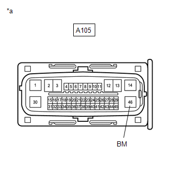
(b) Disconnect the A105 No. 2 skid control ECU (brake actuator assembly) connector.
(c) Check both the connector case and the terminals for deformation and corrosion.
OK:
No deformation or corrosion.
(d) Measure the voltage according to the value(s) in the table below.
Standard Voltage:
|
Tester Connection |
Condition |
Specified Condition |
|---|---|---|
|
A105-46 (BM) - Body ground |
Always |
11 to 14 V |
| NG |

|
REPAIR OR REPLACE HARNESS OR CONNECTOR |
|

|
2. |
CHECK HARNESS AND CONNECTOR (GND2 TERMINAL) |
(a) Measure the resistance according to the value(s) in the table below.
Standard Resistance:
|
Tester Connection |
Condition |
Specified Condition |
|---|---|---|
|
A105-30 (GND2) - Body ground |
1 minute or more after disconnecting the cable from the negative (-) auxiliary battery terminal |
Below 1 Ω |
| NG |
|
REPAIR OR REPLACE HARNESS OR CONNECTOR |
|
|
3. |
CLEAR DTC |
(a) Reconnect the A105 No. 2 skid control ECU (brake actuator assembly) connector.
(b) Clear the DTCs.
Chassis > Brake/EPB > Clear DTCs
(c) Turn the ignition switch off.
|
|
4. |
RECONFIRM DTC |
(a) Based on the Freeze Frame Data and interview with the customer, attempt to reproduce the conditions when the malfunction occurred.
(b) Check if the same DTC is output.
Chassis > Brake/EPB > Trouble Codes
|
Result |
Proceed to |
|---|---|
|
DTCs C052C14, C052C16, C052C17, C052C49 and C052F14 are not output. |
A |
|
DTCs C052C14, C052C16, C052C17, C052C49 and/or C052F14 are output. |
B |
HINT:
- If a speed signal of 20 km/h (12 mph) or more is sent to the No. 2 skid control ECU (brake actuator assembly) with the ignition switch turned to ON and the stop light switch assembly off, the ECU performs self-diagnosis of the motor circuit.
- If the normal system code is output (no DTCs are output), slightly jiggle the connectors, wire harness, and fuses of the No. 2 skid control ECU (brake actuator assembly).
- If any DTCs are output while jiggling a connector or wire harness of the No. 2 skid control ECU (brake actuator assembly), inspect and repair the connector or wire harness.
- If no DTCs were output when reconfirming DTCs, checking for intermittent problems is necessary because it is suspected that the original DTCs were stored due to the poor connection of a connector terminal.
| A |
|
| B |
|
REPLACE BRAKE ACTUATOR ASSEMBLY
|
|
|
|