| Last Modified: 01-30-2024 | 6.11:8.1.0 | Doc ID: RM10000000214PB |
| Model Year Start: 2022 | Model: RAV4 | Prod Date Range: [12/2021 - ] |
| Title: BRAKE CONTROL / DYNAMIC CONTROL SYSTEMS: ELECTRONICALLY CONTROLLED BRAKE SYSTEM (w/o Vacuum Brake Booster): C051223; Right Rear Wheel Speed Sensor Signal Stuck Low; 2022 - 2024 MY RAV4 RAV4 HV [12/2021 - ] | ||
|
DTC |
C051223 |
Right Rear Wheel Speed Sensor Signal Stuck Low |
DESCRIPTION
Refer to DTC C051212.
Click here
![2022 MY RAV4 RAV4 HV [12/2021 - 10/2022]; BRAKE CONTROL / DYNAMIC CONTROL SYSTEMS: ELECTRONICALLY CONTROLLED BRAKE SYSTEM (w/o Vacuum Brake Booster): C051212; Right Rear Wheel Speed Sensor Circuit Short to Battery](/t3Portal/stylegraphics/info.gif)
|
DTC No. |
Detection Item |
DTC Detection Condition |
Trouble Area |
MIL |
Note |
|---|---|---|---|---|---|
|
C051223 |
Right Rear Wheel Speed Sensor Signal Stuck Low |
Any of the following is detected:
|
|
Comes on |
|
C051223 DTC Detection Conditions
|
Vehicle Condition |
||||
|---|---|---|---|---|
|
Pattern 1 |
Pattern 2 |
Pattern 3 |
||
|
Diagnosis Condition |
When the +BS terminal voltage is 17.4 V or less |
○ |
○ |
○ |
|
Malfunction Status |
At a vehicle speed of 10 km/h (6 mph) or more, output voltage from one of the speed sensors is less than that from the other sensors |
○ |
- |
- |
|
At a vehicle speed of 10 km/h (6 mph) or more, output from one of the speed sensors is 0 km/h (0 mph) |
- |
○ |
- |
|
|
At a vehicle speed of 10 km/h (6 mph) or more, outputs from both speed sensors are 0 km/h (0 mph) |
- |
- |
○ |
|
|
Detection Time |
30 seconds or more. |
1 second or more. |
30 seconds or more. |
|
|
Number of Trips |
1 trip |
1 trip |
1 trip |
|
HINT:
DTC will be output when conditions for either of the patterns in the table above are met.
MONITOR DESCRIPTION
When the vehicle is being driven, if the value of the speed sensor which is outputting the lowest vehicle speed is significantly lower than the values of the other speed sensors, or the value of the speed sensor which is outputting the lowest vehicle speed is 0 km/h (0 mph), the No. 2 skid control ECU (brake actuator assembly) judges that the speed sensor is malfunctioning and illuminates the MIL and stores this DTC.
Also, when a wheel speed is being output (the wheel is not locked), if the output values of the speed sensors for 2 wheels are stuck at 0 km/h (0 mph), the No. 2 skid control ECU (brake actuator assembly) judges that a speed sensor is malfunctioning and illuminates the MIL and stores this DTC.
MONITOR STRATEGY
|
Related DTCs |
C0513 (Case 1 to 3): Wheel speed sensor (RR) range/performance |
|
Required Sensors/Components(Main) |
Speed sensor Speed sensor rotor |
|
Required Sensors/Components(Related) |
No. 2 skid control ECU (brake actuator assembly) Stop light switch assembly Speed sensor |
|
Frequency of Operation |
Continuous |
|
Duration |
1 second: C0513 (Case 3) 30 seconds: C0513 (Case 1 and 2) |
|
MIL Operation |
Immediately |
|
Sequence of Operation |
None |
TYPICAL ENABLING CONDITIONS
Case 1
|
Monitor runs whenever the following DTCs are not stored |
C0513 (Case 2 and 4): Wheel speed sensor (RR) range/performance C0514: Wheel speed sensor (RR) voltage circuit open C0515: Wheel speed sensor (RR) voltage circuit high C0516: Wheel speed sensor (RR) intermittent/erratic C1241: Brake system voltage input out of range low C137D: Brake system voltage input out of range high C14EA: Wheel speed sensor (RR) voltage circuit low |
|
All of the following conditions are met |
- |
|
Chassis dynamometer mode |
Off |
|
Command to all ABS hold solenoids |
Off |
|
Command to all ABS release solenoids |
Off |
|
+BS voltage |
17.4 V or less |
|
Difference between the highest speed sensor output value and the second lowest speed sensor output value |
Less than 20% of the highest speed sensor output value |
|
The second lowest speed sensor output value |
13.3 km/h (8.26 mph) or more |
|
IG1 |
On |
Case 2
|
Monitor runs whenever the following DTCs are not stored |
C0513 (Case 4): Wheel speed sensor (RR) range/performance C0514: Wheel speed sensor (RR) voltage circuit open C0515: Wheel speed sensor (RR) voltage circuit high C0516: Wheel speed sensor (RR) intermittent/erratic C1241: Brake system voltage input out of range low C137D: Brake system voltage input out of range high C14EA: Wheel speed sensor (RR) voltage circuit low |
|
All of the following conditions are met |
- |
|
Chassis dynamometer mode |
Off |
|
Command to all ABS hold solenoids |
Off |
|
Command to all ABS release solenoids |
Off |
|
+BS voltage |
17.4 V or less |
|
Brake pedal operation |
Off |
|
Parking brake |
Off |
|
Difference between the highest speed sensor output value and the second highest speed sensor output value |
Less than 20% of the highest speed sensor output value |
|
The second highest speed sensor output value |
13.3 km/h (8.26 mph) or more |
|
IG1 |
On |
Case 3
|
Monitor runs whenever the following DTCs are not stored |
C0501: Wheel speed sensor (FL) range/performance C0502: Wheel speed sensor (FL) voltage circuit open C0503: Wheel speed sensor (FL) voltage circuit high C0504: Wheel speed sensor (FL) intermittent/erratic C0507: Wheel speed sensor (FR) range/performance C0508: Wheel speed sensor (FR) voltage circuit open C0509: Wheel speed sensor (FR) voltage circuit high C050A: Wheel speed sensor (FR) intermittent/erratic C050D: Wheel speed sensor (RL) range/performance C050E: Wheel speed sensor (RL) voltage circuit open C050F: Wheel speed sensor (RL) voltage circuit high C0510: Wheel speed sensor (RL) intermittent/erratic C0513 (Case 1, 2 and 4): Wheel speed sensor (RR) range/performance C0514: Wheel speed sensor (RR) voltage circuit open C0515: Wheel speed sensor (RR) voltage circuit high C0516: Wheel speed sensor (RR) intermittent/erratic C051C: Acceleration sensor range/performance C051D: Acceleration sensor missing calibration C051E: Acceleration sensor intermittent/erratic C0520 (Case 1): Acceleration sensor GL1, GL2 out of range C0520 (Case 2): Acceleration sensor internal malfunction C052B: ABS pump motor performance C052D: ABS pump motor circuit high C052E: ABS pump motor open circuit C053D: Pressure sensor invalid data C0540 (Case 1): Pressure sensor verify communication C0540 (Case 2 to 4): Pressure sensor range check C055B: ABS pump motor voltage circuit low C056B: Pressure sensor intermittent/erratic C0597 (Case 1): ABS hold solenoid circuit stuck C0597 (Case 2 to 5): ABS hold solenoid performance C05C1: Brake pedal position sensor learning not complete C1103 (Case 1): Brake pedal position sensor voltage circuit/open C1103 (Case 2): Brake pedal position sensor invalid data C1202: Reservoir level too low C120F: Reservoir level switch open circuit C122E: Pressure sensor input out of range low C122F: Pressure sensor input out of range high C1240: Yaw rate and acceleration sensor incorrect C1241: Brake system voltage input out of range low C124A: Identification signal C12A7: ABS hold solenoid (FL) circuit low C12A8: ABS hold solenoid (FL) circuit high C12B2: ABS release solenoid (FL) circuit low C12B3: ABS release solenoid (FL) circuit high C12BD: ABS hold solenoid (FR) circuit low C12BE: ABS hold solenoid (FR) circuit high C12C8: ABS release solenoid (FR) circuit low C12C9: ABS release solenoid (FR) circuit high C12D3: ABS hold solenoid (RL) circuit low C12D4: ABS hold solenoid (RL) circuit high C12DE: ABS release solenoid (RL) circuit low C12DF: ABS release solenoid (RL) circuit high C12E9: ABS hold solenoid (RR) circuit low C12EA: ABS hold solenoid (RR) circuit high C12F4: ABS release solenoid (RR) circuit low C12F5: ABS release solenoid (RR) circuit high C12F6: ABS hold solenoid other functional C12F7: ABS hold solenoid other functional C137C: Brake system voltage input out of range low C137D: Brake system voltage input out of range high C13BF: SM solenoid other functional C13C2: SM1 solenoid circuit low C13C3: SM1 solenoid circuit high C13CB: SM2 solenoid circuit low C13CC: SM2 solenoid circuit high C1427: ABS pump motor stuck C143B: Brake system voltage solenoid relay stuck C143C: Brake system voltage open circuit C14D7: Acceleration sensor voltage circuit/open C14E1: Wheel speed sensor (FL) voltage circuit low C14E4: Wheel speed sensor (FR) voltage circuit low C14E7: Wheel speed sensor (RL) voltage circuit low C14EA: Wheel speed sensor (RR) voltage circuit low P05DB: Brake pedal position sensor invalid data P05DD: Brake pedal position sensor open circuit P05DE: Brake pedal position sensor circuit high P05DF: Brake pedal position sensor intermittent/erratic P05E0: Brake pedal position sensor "A"/"B" correlation U0074 (Case 1): Late communication with multi-axis acceleration sensor module U0074 (Case 2): Late communication with steer sensor module U0125: Lost communication with multi-axis acceleration sensor module U025E: Lost communication with electronic brake booster control unit (C-Bus) |
|
All of the following conditions are met |
- |
|
Chassis dynamometer mode |
Off |
|
Command to all ABS hold solenoids |
Off |
|
Command to all ABS release solenoids |
Off |
|
+BS voltage |
17.4 V or less |
|
Brake pedal operation |
Off |
|
Parking brake |
Off |
|
Difference between the highest speed sensor output value and the second lowest speed sensor output value |
Less than 2 km/h (1.24 mph) |
|
The second lowest speed sensor output value |
13.3 km/h (8.26 mph) or more |
|
IG1 |
On |
TYPICAL MALFUNCTION THRESHOLDS
Case 1
|
All of the following conditions are met |
A and B |
|
A. One-seventh of the second lowest speed sensor output value |
Higher than the lowest speed sensor output value |
|
B. Either of the following conditions is met |
- |
|
Drive type |
2WD |
|
Drive type |
4WD/AWD |
Case 2
|
All of the following conditions are met |
A and B |
|
A. Second lowest speed sensor output value |
0 km/h (0 mph) |
|
B. Either of the following conditions is met |
- |
|
Drive type |
2WD |
|
Drive type |
4WD/AWD |
Case 3
|
All of the following conditions are met |
- |
|
Chassis dynamometer mode |
Off |
|
Lowest speed sensor output value |
0 km/h (0 mph) |
|
Elapse time since second lowest speed sensor value changed from less than V4 to equal to or greater than V4 |
1 second or less |
COMPONENT OPERATING RANGE
All
|
All of the following conditions are met |
- |
|
Chassis dynamometer mode |
Off |
|
Wheel speed sensor fail (C0502, C0503, C14E1, C0508, C0509, C14E4, C050E, C050F, C14E7, C0514, C0515, C14EA) |
Not detected |
|
Wheel speed sensor pass flag |
On |
CONFIRMATION DRIVING PATTERN
NOTICE:
When performing the normal judgment procedure, make sure that the driver door is closed and is not opened at any time during the procedure.
HINT:
- After repair has been completed, clear the DTC and then check that the vehicle has returned to normal by performing the following All Readiness check procedure.
- When clearing the permanent DTCs, refer to the "CLEAR PERMANENT DTC" procedure.
- Connect the GTS to the DLC3.
- Turn the ignition switch to ON and turn the GTS on.
- Clear the DTCs (even if no DTCs are stored, perform the clear DTC procedure).
- Turn the ignition switch off.
- Turn the ignition switch to ON (READY) and turn the GTS on.
-
Drive the vehicle straight at a speed of 20 km/h (12 mph) or more for 30 seconds or more. [*]
HINT:
[*]: Normal judgment procedure.
The normal judgment procedure is used to complete DTC judgment and also used when clearing permanent DTCs.
- Enter the following menus: Chassis / Brake/EPB / Utility / All Readiness.
-
Check the DTC judgment result.
HINT:
- If the judgment result shows NORMAL, the system is normal.
- If the judgment result shows ABNORMAL, the system has a malfunction.
- If the judgment result shows INCOMPLETE, perform driving pattern again.
WIRING DIAGRAM
Refer to DTC C051212.
Click here
CAUTION / NOTICE / HINT
NOTICE:
-
After replacing or removing and installing a skid control sensor, perform Dealer Mode (Signal Check) inspection to confirm that the skid control sensors are operating correctly.
Click here
-
After replacing or removing and installing a speed sensor rotor, perform Dealer Mode (Signal Check) inspection to confirm that the skid control sensors are operating correctly.
Click here
PROCEDURE
|
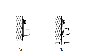
1. |
CHECK REAR SKID CONTROL SENSOR RH INSTALLATION |
|
(a) Check the rear skid control sensor RH installation. OK: There is no clearance between the rear skid control sensor RH and the rear axle carrier RH. |
|
| NG |

|
|

|
2. |
CHECK REAR SKID CONTROL SENSOR RH (CHECK FOR FOREIGN MATTER) |
(a) Remove the rear skid control sensor RH.
Click here
(b) Check the rear skid control sensor tip RH.
OK:
The rear skid control sensor tip RH is free of scratches, oil, and foreign matter.
NOTICE:
- If there is oil or foreign matter on the rear skid control sensor RH, clean the rear skid control sensor RH.
- If the rear skid control sensor RH is damaged, replace the rear skid control sensor RH with a new one.
| NG |
|
CLEAN OR REPLACE REAR SKID CONTROL SENSOR RH |
|
|
3. |
READ VALUE USING GTS (RR WHEEL SPEED) |
(a) Perform a road test.
(b) Check the rear skid control sensor RH output value.
Chassis > Brake/EPB > Data List
|
Tester Display |
Measurement Item |
Range |
Normal Condition |
Diagnostic Note |
|---|---|---|---|---|
|
RR Wheel Speed |
Rear wheel speed sensor RH reading |
Min.: 0.0 km/h (0 mph) Max.: 6553.5 km/h (4072 mph) |
Vehicle stopped: 0.0 km/h (0 mph) |
When driving at constant speed: No large fluctuations |
Chassis > Brake/EPB > Data List
|
Tester Display |
|---|
|
RR Wheel Speed |
OK:
The output value changes in accordance with the vehicle speed.
| OK |
|
|
|
4. |
INSPECT NO. 1 PARKING BRAKE WIRE ASSEMBLY |
|
(a) Turn the ignition switch off. |
|
(b) Make sure that there is no looseness at the locking part and the connecting part of the connectors.
OK:
The connector is securely connected.
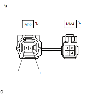
(c) Disconnect the M50 and MM4 skid control sensor wire RH (No. 1 parking brake wire assembly) connector.
(d) Check both the connector case and the terminals for deformation and corrosion.
OK:
No deformation or corrosion.
(e) Measure the resistance according to the value(s) in the table below.
Standard Resistance:
|
Tester Connection |
Condition |
Specified Condition |
|---|---|---|
|
M50-2 (+) - MM4-3 |
Always |
Below 1 Ω |
|
M50-2 (+) or MM4-3 - Body ground and other terminals |
Always |
10 kΩ or higher |
|
M50-1 (-) - MM4-4 |
Always |
Below 1 Ω |
|
M50-1 (-) or MM4-4 - Body ground and other terminals |
Always |
10 kΩ or higher |
| NG |
|
REPLACE NO. 1 PARKING BRAKE WIRE ASSEMBLY |
|
|
5. |
CHECK HARNESS AND CONNECTOR (NO. 1 PARKING BRAKE WIRE ASSEMBLY - BRAKE ACTUATOR ASSEMBLY) |
(a) Make sure that there is no looseness at the locking part and the connecting part of the connectors.
OK:
The connector is securely connected.
(b) Disconnect the A105 No. 2 skid control ECU (brake actuator assembly) connector.
(c) Check both the connector case and the terminals for deformation and corrosion.
OK:
No deformation or corrosion.
(d) Measure the resistance according to the value(s) in the table below.
Standard Resistance:
|
Tester Connection |
Condition |
Specified Condition |
|---|---|---|
|
MM4-3 - A105-20 (RR+) |
Always |
Below 1 Ω |
|
MM4-3 or A105-20 (RR+) - Body ground |
Always |
10 kΩ or higher |
|
MM4-4 - A105-19 (RR-) |
Always |
Below 1 Ω |
|
MM4-4 or A105-19 (RR-) - Body ground |
Always |
10 kΩ or higher |
| NG |
|
REPAIR OR REPLACE HARNESS OR CONNECTOR |
|
|
6. |
CHECK REAR SPEED SENSOR ROTOR RH (CHECK FOR FOREIGN MATTER) |
(a) Remove the component with the rear speed sensor rotor RH.
Click here
(b) Check the rear speed sensor rotor RH.
OK:
The rear speed sensor rotor RH is free of scratches, oil, and foreign matter.
NOTICE:
- If there is oil or foreign matter on the rear speed sensor rotor RH, clean the rear speed sensor rotor RH.
- Do not use parts cleaner when cleaning the rear speed sensor rotor RH.
- If the rear speed sensor rotor RH is damaged, replace the rear speed sensor rotor RH with a new one.
HINT:
The rear speed sensor rotor RH is incorporated into the rear axle hub and bearing assembly RH.
If the rear speed sensor rotor RH needs to be replaced, replace it together with the rear axle hub and bearing assembly RH.
|
Result |
Proceed to |
|---|---|
|
OK |
A |
|
NG (The rear speed sensor rotor RH is damaged.) |
B |
|
NG (There is foreign matter on the rear speed sensor rotor RH.) |
C |
| A |
|
| B |
|
REPLACE REAR AXLE HUB AND BEARING ASSEMBLY RH
|
| C |
|
CLEAN REAR SPEED SENSOR ROTOR RH |
|
|
|