| Last Modified: 01-30-2024 | 6.11:8.1.0 | Doc ID: RM10000000214P9 |
| Model Year Start: 2022 | Model: RAV4 | Prod Date Range: [12/2021 - ] |
| Title: BRAKE CONTROL / DYNAMIC CONTROL SYSTEMS: ELECTRONICALLY CONTROLLED BRAKE SYSTEM (w/o Vacuum Brake Booster): C051214; Right Rear Wheel Speed Sensor Circuit Short to Ground or Open; 2022 - 2024 MY RAV4 RAV4 HV [12/2021 - ] | ||
|
DTC |
C051214 |
Right Rear Wheel Speed Sensor Circuit Short to Ground or Open |
DESCRIPTION
Refer to DTC C051212.
Click here
![2022 MY RAV4 RAV4 HV [12/2021 - 10/2022]; BRAKE CONTROL / DYNAMIC CONTROL SYSTEMS: ELECTRONICALLY CONTROLLED BRAKE SYSTEM (w/o Vacuum Brake Booster): C051212; Right Rear Wheel Speed Sensor Circuit Short to Battery](/t3Portal/stylegraphics/info.gif)
|
DTC No. |
Detection Item |
DTC Detection Condition |
Trouble Area |
MIL |
Note |
|---|---|---|---|---|---|
|
C051214 |
Right Rear Wheel Speed Sensor Circuit Short to Ground or Open |
An open in the speed sensor signal circuit continues for 0.5 seconds or more. |
|
Comes on |
|
MONITOR DESCRIPTION
The No. 2 skid control ECU (brake actuator assembly) monitors the output of the speed sensor. When the output current of the speed sensor is excessively low, the MIL is illuminated and a DTC is stored.
MONITOR STRATEGY
|
Related DTCs |
C0514: Wheel speed sensor (RR) voltage circuit open |
|
Required Sensors/Components(Main) |
Speed sensor |
|
Required Sensors/Components(Related) |
No. 2 skid control ECU (brake actuator assembly) |
|
Frequency of Operation |
Continuous |
|
Duration |
0.528 seconds |
|
MIL Operation |
Immediately |
|
Sequence of Operation |
None |
TYPICAL ENABLING CONDITIONS
|
Monitor runs whenever the following DTCs are not stored |
C0513 (Case 4): Wheel speed sensor (RR) range/performance C0515: Wheel speed sensor (RR) voltage circuit high C137D: Brake system voltage input out of range high C14EA: Wheel speed sensor (RR) voltage circuit low |
|
All of the following conditions are met |
- |
|
+BS voltage |
17.4 V or less |
|
Command to wheel speed sensor power supply |
On |
|
Vehicle speed sensor supply voltage state |
Valid |
|
Wheel speed sensor current |
Less than 0.034 A |
TYPICAL MALFUNCTION THRESHOLDS
|
Wheel speed sensor current |
0.004 A or less |
COMPONENT OPERATING RANGE
|
Wheel speed sensor current |
Higher than 0.004 A |
CONFIRMATION DRIVING PATTERN
NOTICE:
When performing the normal judgment procedure, make sure that the driver door is closed and is not opened at any time during the procedure.
HINT:
- After repair has been completed, clear the DTC and then check that the vehicle has returned to normal by performing the following All Readiness check procedure.
- When clearing the permanent DTCs, refer to the "CLEAR PERMANENT DTC" procedure.
- Connect the GTS to the DLC3.
- Turn the ignition switch to ON and turn the GTS on.
- Clear the DTCs (even if no DTCs are stored, perform the clear DTC procedure).
- Turn the ignition switch off.
- Turn the ignition switch to ON (READY) and turn the GTS on.
-
Wait for 2 seconds or more. [*]
HINT:
[*]: Normal judgment procedure.
The normal judgment procedure is used to complete DTC judgment and also used when clearing permanent DTCs.
- Enter the following menus: Chassis / Brake/EPB / Utility / All Readiness.
-
Check the DTC judgment result.
HINT:
- If the judgment result shows NORMAL, the system is normal.
- If the judgment result shows ABNORMAL, the system has a malfunction.
- If the judgment result shows INCOMPLETE, perform driving pattern again.
WIRING DIAGRAM
Refer to DTC C051212.
Click here
CAUTION / NOTICE / HINT
NOTICE:
-
After replacing the No. 2 skid control ECU (brake actuator assembly), perform "Calibration" after performing "Reset Memory".
Click here
-
After replacing or removing and installing a skid control sensor, perform Dealer Mode (Signal Check) inspection to confirm that the skid control sensors are operating correctly.
Click here
PROCEDURE
|
1. |
READ VALUE USING GTS (MOMENTARY INTERRUPTION) |
(a) Select the line graph display on the GTS.
(b) Check for any momentary interruption in the wire harness and connector.
Click here
Chassis > Brake/EPB > Data List
|
Tester Display |
Measurement Item |
Range |
Normal Condition |
Diagnostic Note |
|---|---|---|---|---|
|
RR Speed Open |
Momentary interruption of rear skid control sensor RH pulse input to ECU |
Normal / Under intermittent |
Normal: Normal Under intermittent: Momentary interruption |
- |
|
RR Speed Sensor Voltage Open |
Rear skid control sensor RH voltage open detection |
Normal / Under intermittent |
Normal: Normal Under intermittent: Momentary interruption |
- |
Chassis > Brake/EPB > Data List
|
Tester Display |
|---|
|
RR Speed Open |
|
RR Speed Sensor Voltage Open |
OK:
Normal (There are no momentary interruptions.)
NOTICE:
Perform the above inspection before removing the sensor and connector.
| OK |

|
|

|
2. |
INSPECT NO. 1 PARKING BRAKE WIRE ASSEMBLY |
|
(a) Turn the ignition switch off. |
|
(b) Make sure that there is no looseness at the locking part and the connecting part of the connectors.
OK:
The connector is securely connected.
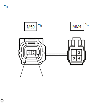
(c) Disconnect the M50 and MM4 skid control sensor wire RH (No. 1 parking brake wire assembly) connector.
(d) Check both the connector case and the terminals for deformation and corrosion.
OK:
No deformation or corrosion.
(e) Measure the resistance according to the value(s) in the table below.
Standard Resistance:
|
Tester Connection |
Condition |
Specified Condition |
|---|---|---|
|
M50-2 (+) - MM4-3 |
Always |
Below 1 Ω |
|
M50-2 (+) or MM4-3 - Body ground and other terminals |
Always |
10 kΩ or higher |
|
M50-1 (-) - MM4-4 |
Always |
Below 1 Ω |
|
M50-1 (-) or MM4-4 - Body ground and other terminals |
Always |
10 kΩ or higher |
| NG |
|
REPLACE NO. 1 PARKING BRAKE WIRE ASSEMBLY |
|
|
3. |
CHECK HARNESS AND CONNECTOR (NO. 1 PARKING BRAKE WIRE ASSEMBLY - BRAKE ACTUATOR ASSEMBLY) |
(a) Make sure that there is no looseness at the locking part and the connecting part of the connectors.
OK:
The connector is securely connected.
(b) Disconnect the A105 No. 2 skid control ECU (brake actuator assembly) connector.
(c) Check both the connector case and the terminals for deformation and corrosion.
OK:
No deformation or corrosion.
(d) Measure the resistance according to the value(s) in the table below.
Standard Resistance:
|
Tester Connection |
Condition |
Specified Condition |
|---|---|---|
|
MM4-3 - A105-20 (RR+) |
Always |
Below 1 Ω |
|
MM4-3 or A105-20 (RR+) - Body ground |
Always |
10 kΩ or higher |
|
MM4-4 - A105-19 (RR-) |
Always |
Below 1 Ω |
|
MM4-4 or A105-19 (RR-) - Body ground |
Always |
10 kΩ or higher |
| NG |
|
REPAIR OR REPLACE HARNESS OR CONNECTOR |
|
|
4. |
INSPECT BRAKE ACTUATOR ASSEMBLY (SENSOR POWER SOURCE CIRCUIT) |
|
(a) Reconnect the A105 No. 2 skid control ECU (brake actuator assembly) connector. |
|
(b) Reconnect the MM4 skid control sensor wire RH (No. 1 parking brake wire assembly) connector.
(c) Turn the ignition switch to ON.
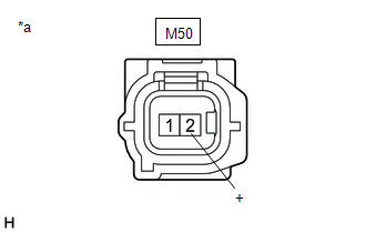
(d) Measure the voltage according to the value(s) in the table below.
Standard Voltage:
|
Tester Connection |
Condition |
Specified Condition |
|---|---|---|
|
M50-2 (+) - Body ground |
Ignition switch ON |
11 to 14 V |
| OK |
|
| NG |
|
REPLACE BRAKE ACTUATOR ASSEMBLY
|
|
|
|