| Last Modified: 01-30-2024 | 6.11:8.1.0 | Doc ID: RM10000000214ON |
| Model Year Start: 2022 | Model: RAV4 | Prod Date Range: [12/2021 - ] |
| Title: BRAKE CONTROL / DYNAMIC CONTROL SYSTEMS: ELECTRONICALLY CONTROLLED BRAKE SYSTEM (w/o Vacuum Brake Booster): DATA LIST / ACTIVE TEST; 2022 - 2024 MY RAV4 RAV4 HV [12/2021 - ] | ||
DATA LIST / ACTIVE TEST
DATA LIST
NOTICE:
In the table below, the values listed under "Normal Condition" are reference values. Do not depend solely on these reference values when deciding whether a part is faulty or not.
HINT:
Using the GTS to read the Data List allows the values or states of switches, sensors, actuators and other items to be read without removing any parts. This non-intrusive inspection can be very useful because intermittent conditions or signals may be discovered before parts or wiring is disturbed. Reading the Data List information early in troubleshooting is one way to save diagnostic time.
(a) According to the display on the GTS, read the Data List.
Chassis > Brake Booster > Data List
|
Tester Display |
Measurement Item |
Range |
Normal Condition |
Diagnostic Note |
|---|---|---|---|---|
|
Total Distance Traveled - Unit |
Total Distance Traveled unit |
km / mile |
- |
- |
|
Total Distance Traveled |
Total distance traveled |
Min.: 0 Max.: 16777215 |
- |
- |
|
IG1 Voltage Value |
Ignition switch ON status |
OFF / ON |
- |
- |
|
Stop Light SW |
Stop light switch assembly (STP terminal input) |
OFF / ON |
OFF: Brake pedal released ON: Brake pedal depressed |
HINT: The brake pedal state is determined using the voltage at terminal STP |
|
Parking Brake SW |
Parking brake status |
OFF / ON |
OFF: Parking brake released ON: Parking brake applied |
- |
|
Buzzer |
Meter buzzer |
OFF / ON |
OFF: Buzzer off ON: Buzzer on |
- |
|
Dealer Mode |
Dealer Mode (Signal Check mode or Calibration mode) status |
OFF / ON |
OFF: Normal mode ON: Dealer Mode (Signal Check mode or Calibration mode) |
HINT:
|
|
Reservoir Warning SW |
Brake fluid level warning switch status |
OFF / ON |
OFF: Reservoir level normal ON: Reservoir level low |
- |
|
ECB Motor Relay |
Motor relay operation request |
OFF / ON |
OFF: Relay off ON: Relay on |
ECB: Electronically Controlled Brake System |
|
ECB Solenoid (SGH) |
Switching solenoid valve (SGH) |
OFF / ON |
OFF: Solenoid off ON: Solenoid on |
ECB: Electronically Controlled Brake System |
|
ECB Solenoid (SSA) |
Switching solenoid valve (SSA) |
OFF / ON |
OFF: Solenoid off ON: Solenoid on |
ECB: Electronically Controlled Brake System |
|
Reaction Force Pressure |
Pressure value of stroke simulator |
Min.: 0.00 MPa Max.: 24.48 MPa |
Brake pedal released: 0.00 to 1.53 MPa |
Brake pedal is being depressed: Changes in proportion to the depression force of the brake pedal |
|
Stroke Sensor |
Brake pedal stroke sensor 1 |
Min.: 0.0 V Max.: 5.0 V |
Brake pedal released: 0.6 to 1.4 V |
Reading increases when brake pedal is depressed |
|
Quantity of Brake Pedal Stroke |
Brake pedal stroke amount |
Min.: 0 mm Max.: 255 mm |
Brake pedal released: 0 mm |
- |
|
Servo Pressure |
Pressure value of servo |
Min.: 0.00 MPa Max.: 24.48 MPa |
Brake pedal released: 0.00 to 1.53 MPa |
Brake pedal is being depressed: Changes in proportion to the depression force of the brake pedal |
|
Accumulator Pressure |
Accumulator pressure output value |
Min.: 0.00 MPa Max.: 24.48 MPa |
15.00 to 21.00 MPa (Pressure stable and pump motor stopped) |
When brake fluid is stored in the accumulator: Accumulator pressure changes in accordance with volume of fluid stored in the accumulator |
|
Voltage of Stroke Sensor |
Voltage of brake pedal stroke sensor 1 |
Min.: 0.000 V Max.: 5.000 V |
- |
- |
|
Brake Pedal Stroke Change Speed |
Brake pedal stroke rate of change |
Min.: -2560 mm/s Max.: 2540 mm/s |
Brake pedal released or depressed and held: 0 mm/s |
Brake pedal is being moved: Changes in proportion to the operation speed of the brake pedal |
|
Reaction Force Oil Pressure Change Speed |
Reaction force pressure rate of change |
Min.: -30 MPa/s Max.: 225 MPa/s |
- |
- |
|
Target Oil Pressure |
Wheel target hydraulic pressure |
Min.: 0.00 MPa Max.: 20.00 MPa |
- |
Changes according to the target wheel cylinder hydraulic pressure |
|
VCSK Voltage Value |
VCSK voltage value |
Min.: 0.000 V Max.: 5.500 V |
4.800 to 5.200 V |
- |
|
SLA Solenoid Current |
Linear solenoid addition valve (SLA) current |
Min.: 0.000 A Max.: 1.500 A |
Brake pedal released: 0.000 A |
- |
|
SLR Solenoid Current |
Linear solenoid reduction valve (SLR) current |
Min.: 0.000 A Max.: 1.500 A |
Brake pedal released: 0.000 A |
- |
|
SGH Solenoid Current |
Switching solenoid valve (SGH) current |
Min.: 0.000 A Max.: 3.000 A |
0.000 to 1.500 A |
- |
|
SSA Solenoid Current |
Switching solenoid valve (SSA) current |
Min.: 0.000 A Max.: 3.000 A |
0.000 to 1.500 A |
- |
|
ECB Main Relay |
Main relay operation request |
OFF / ON |
OFF: Relay off ON: Relay on |
ECB: Electronically Controlled Brake System |
|
IG1 Voltage |
IG1 voltage value |
Min.: 0.000 V Max.: 20.000 V |
- |
Changes in proportion to auxiliary battery voltage |
|
IG2 Voltage |
IG2 voltage value |
Min.: 0.000 V Max.: 20.000 V |
- |
Changes in proportion to auxiliary battery voltage |
|
BI Voltage |
+BI1 voltage value |
Min.: 0.000 V Max.: 20.000 V |
- |
Changes in proportion to auxiliary battery voltage |
|
BS Voltage |
BS voltage value |
Min.: 0.000 V Max.: 20.000 V |
- |
Changes in proportion to auxiliary battery voltage |
-
*1: for performing Dealer Mode (Signal Check): Click here
![2022 - 2024 MY RAV4 RAV4 HV [12/2021 - ]; BRAKE CONTROL / DYNAMIC CONTROL SYSTEMS: ELECTRONICALLY CONTROLLED BRAKE SYSTEM (w/o Vacuum Brake Booster): TEST MODE PROCEDURE](/t3Portal/stylegraphics/info.gif)
*2: for entering Dealer Mode (Calibration): Click here
Chassis > Brake/EPB > Data List
|
Tester Display |
Measurement Item |
Range |
Normal Condition |
Diagnostic Note |
|---|---|---|---|---|
|
Total Distance Traveled - Unit |
Total Distance Traveled unit |
km / mile |
- |
- |
|
Total Distance Traveled |
Total distance traveled |
Min.: 0 Max.: 16777215 |
- |
- |
|
FR Wheel Speed |
Front wheel speed sensor RH reading |
Min.: 0.0 km/h (0 mph) Max.: 6553.5 km/h (4072 mph) |
Vehicle stopped: 0.0 km/h (0 mph) |
When driving at constant speed: No large fluctuations |
|
FL Wheel Speed |
Front wheel speed sensor LH reading |
Min.: 0.0 km/h (0 mph) Max.: 6553.5 km/h (4072 mph) |
Vehicle stopped: 0.0 km/h (0 mph) |
When driving at constant speed: No large fluctuations |
|
RR Wheel Speed |
Rear wheel speed sensor RH reading |
Min.: 0.0 km/h (0 mph) Max.: 6553.5 km/h (4072 mph) |
Vehicle stopped: 0.0 km/h (0 mph) |
When driving at constant speed: No large fluctuations |
|
RL Wheel Speed |
Rear wheel speed sensor LH reading |
Min.: 0.0 km/h (0 mph) Max.: 6553.5 km/h (4072 mph) |
Vehicle stopped: 0.0 km/h (0 mph) |
When driving at constant speed: No large fluctuations |
|
FR Wheel Acceleration |
Front wheel RH acceleration |
Min.: -200.840 m/s2 Max.: 199.271 m/s2 |
- |
During deceleration/acceleration: Changes continuously |
|
FL Wheel Acceleration |
Front wheel LH acceleration |
Min.: -200.840 m/s2 Max.: 199.271 m/s2 |
- |
During deceleration/acceleration: Changes continuously |
|
RR Wheel Acceleration |
Rear wheel RH acceleration |
Min.: -200.840 m/s2 Max.: 199.271 m/s2 |
- |
During deceleration/acceleration: Changes continuously |
|
RL Wheel Acceleration |
Rear wheel LH acceleration |
Min.: -200.840 m/s2 Max.: 199.271 m/s2 |
- |
During deceleration/acceleration: Changes continuously |
|
Master Cylinder Sensor 1 |
Master cylinder pressure sensor pressure (value detected by ECU) |
Min.: -1.00 MPa Max.: 23.99 MPa |
Brake pedal released: -1.00 to 0.00 MPa |
Reading increases when brake pedal is depressed |
|
Zero Point of M/C |
Memorized zero point value of master cylinder pressure sensor |
Min.: -12.5 MPa Max.: 12.4 MPa |
- |
- |
|
Master Cylinder Sensor Temperature |
Master cylinder pressure sensor temperature |
Min.: -80°C (-112°F) Max.: 175°C (347°F) |
Current master cylinder pressure sensor temperature |
- |
|
M/C Sensor Grade |
Master cylinder pressure sensor change (value detected by ECU) |
Min.: -30 MPa/s Max.: 225 MPa/s |
Brake pedal released or pedal held at constant position: 0 MPa/s |
When brake pedal is being operated: Changes in proportion with the pedal movement speed |
|
Lateral G |
Lateral G |
Min.: -25.105 m/s2 Max.: 24.908 m/s2 |
Turning right: -25.105 to 0.000 m/s2 Turning left: 0.000 to 24.908 m/s2 |
During turning: Changes in proportion with lateral acceleration |
|
Forward and Rearward G |
Forward and rearward G |
Min.: -25.105 m/s2 Max.: 24.908 m/s2 |
During deceleration: -25.105 to 0.000 m/s2 During acceleration: 0.000 to 24.908 m/s2 |
During acceleration/deceleration: Changes in proportion with acceleration |
|
Zero Point of Decele2 |
Memorized zero point value of lateral G |
Min.: -25.105 m/s2 Max.: 24.908 m/s2 |
- |
- |
|
Zero Point of Decele |
Memorized zero point value of forward and rearward G |
Min.: -25.105 m/s2 Max.: 24.908 m/s2 |
- |
- |
|
Yaw Rate Sensor Value |
Yaw rate sensor |
Min.: -128°/s Max.: 127°/s |
Vehicle stopped: 0°/s Turning right: -128 to 0°/s Turning left: 0 to 127°/s |
- |
|
Zero Point of Yaw Rate Sensor |
Memorized zero point value of yaw rate sensor 1 |
Min.: -128°/s Max.: 127°/s |
After completing zero point calibration: 0° |
- |
|
Steering Angle Value |
Steering sensor |
Min.: -3276.8° Max.: 3276.7° |
Turning left: 0.0 to 3276.7° Turning right: -3276.8 to 0.0° |
- |
|
Zero Point of Steering Angle |
Memorized zero point value of steering sensor |
Min.: -3276.8° Max.: 3276.7° |
- |
- |
|
MT Voltage Value |
ABS motor drive voltage value |
Min.: 0.0 V Max.: 25.5 V |
Ignition switch ON: 0.0 to 4.7 V |
Changes in proportion to auxiliary battery voltage HINT: This is the voltage downstream of the ABS motor as monitored by the No. 2 skid control ECU |
|
Solenoid Power Supply Voltage |
Solenoid power supply voltage value |
Min.: 0.0 V Max.: 25.5 V |
Ignition switch ON: 11.0 to 14.0 V |
Changes in proportion to auxiliary battery voltage HINT: This is the voltage output (which supplies power to each solenoid) from the No. 2 skid control ECU (brake actuator assembly) to the ABS solenoid relay |
|
Vehicle Speed |
Vehicle speed (Vehicle speed signal output to combination meter assembly) |
Min.: 0.0 km/h (0 mph) Max.: 6553.5 km/h (4072 mph) |
Vehicle stopped: 0.0 km/h (0 mph) |
When driving at constant speed: No large fluctuations |
|
Accelerator Opening Angle % |
Percentage of accelerator pedal opening angle |
Min.: 0.0% Max.: 127.5% |
Accelerator pedal released: 0.0% |
During accelerator pedal operation: Changes in proportion with the pedal movement |
|
Shift Lever Position |
Shift lever position information |
fail / 1st / 2nd / 3rd / 4th / 5th / 6th / B / D/M / N / P / R / No input |
Actual shift lever position |
- |
|
TRC(TRAC)/VSC OFF Mode |
TRAC/VSC off mode |
Normal mode (TRC(TRAC) ON/VSC ON) / TRC(TRAC) OFF mode (TRC(TRAC) OFF/VSC ON) / Not defined / VSC OFF mode (TRC(TRAC) OFF/VSC OFF) |
Normal mode (TRC(TRAC) ON/VSC ON): Normal mode TRC(TRAC) OFF mode (TRC(TRAC) OFF/VSC ON): TRAC off mode Not defined: Not defined VSC OFF mode (TRC(TRAC) OFF/VSC OFF): VSC off mode |
- |
|
Brake Hold Control Mode |
Brake hold control mode |
Out of control mode / Pressure hold mode / Pressure release mode / EPB lock mode |
Out of control mode: Brake hold control system is off or brake hold control system is stand-by mode (brake hold standby indicator light is illuminated) Pressure hold mode: Brake hold control is operating (brake hold operated indicator light is illuminated) Pressure release mode: Brake hold control is released (brake hold operated indicator light not illuminated) EPB lock mode: Parking brake is engaged during brake hold control |
HINT:
|
|
FR Target Oil Pressure |
Front wheel RH target oil pressure |
Min.: 0.0 MPa Max.: 20.0 MPa |
- |
Different according to target oil pressure of each wheel |
|
FL Target Oil Pressure |
Front wheel LH target oil pressure |
Min.: 0.0 MPa Max.: 20.0 MPa |
- |
Different according to target oil pressure of each wheel |
|
RR Target Oil Pressure |
Rear wheel RH target oil pressure |
Min.: 0.0 MPa Max.: 20.0 MPa |
- |
Different according to target oil pressure of each wheel |
|
RL Target Oil Pressure |
Rear wheel LH target oil pressure |
Min.: 0.0 MPa Max.: 20.0 MPa |
- |
Different according to target oil pressure of each wheel |
|
Vehicle Speed Grade |
Vehicle acceleration/deceleration |
Min.: -25.105 m/s2 Max.: 24.908 m/s2 |
Vehicle stopped: 0.000 m/s2 During deceleration: -25.105 to 0.000 m/s2 During acceleration: 0.000 to 24.908 m/s2 |
During driving: Changes in proportion with vehicle acceleration/deceleration |
|
Vehicle Stop Time from IG ON |
Time vehicle stopped after ignition switch turned to ON |
Min.: 0 s Max.: 1275 s |
- |
- |
|
Travel Distance from IG ON |
Driving time after ignition switch turned to ON |
Min.: 0 s Max.: 1275 s |
- |
- |
|
IG Switch |
Ignition switch ON status |
OFF / ON |
- |
- |
|
Stop Light SW |
Stop light switch assembly status (STP or STP2 terminal input) |
OFF / ON |
OFF: Brake pedal released ON: Brake pedal depressed |
HINT:
|
|
Parking Brake SW |
Parking brake status |
OFF / ON |
OFF: Parking brake released ON: Parking brake applied |
- |
|
Brake Hold Switch |
Brake hold switch (integration control and panel assembly) (BH terminal input) |
OFF / ON |
OFF: Brake hold switch (integration control and panel assembly) OFF ON: Brake hold switch (integration control and panel assembly) ON |
HINT: The brake hold switch (integration control and panel assembly) state is determined using the voltage at terminal BH |
|
Stop Light Relay |
Stop light control relay (Stop light switch assembly) status (STP terminal input) |
OFF / ON |
OFF: Stop light control relay (Stop light switch assembly) off and brake pedal released ON: Stop light control relay (Stop light switch assembly) on or brake pedal depressed |
HINT: The voltage of power supplied to the stop lights is measured at the STP terminal. |
|
Inspection Mode |
Inspection mode |
OFF / ON |
OFF: Normal mode ON: Inspection mode |
- |
|
TRC(TRAC) Control |
TRAC control status |
Out of controlling / Under Controlling |
Out of controlling: During not control Under Controlling: During control |
- |
|
TRC(TRAC) Engine Control |
TRAC engine control status |
Out of controlling / Under Controlling |
Out of controlling: During not control Under Controlling: During control |
- |
|
TRC(TRAC) Brake Control |
TRAC brake control status |
Out of controlling / Under Controlling |
Out of controlling: During not control Under Controlling: During control |
- |
|
FR Wheel VSC Ctrl Status |
Front wheel RH VSC control status |
Out of controlling / Under Controlling |
Out of controlling: During not control Under Controlling: During control |
- |
|
FL Wheel VSC Ctrl Status |
Front wheel LH VSC control status |
Out of controlling / Under Controlling |
Out of controlling: During not control Under Controlling: During control |
- |
|
RR Wheel VSC Ctrl Status |
Rear wheel RH VSC control status |
Out of controlling / Under Controlling |
Out of controlling: During not control Under Controlling: During control |
- |
|
RL Wheel VSC Ctrl Status |
Rear wheel LH VSC control status |
Out of controlling / Under Controlling |
Out of controlling: During not control Under Controlling: During control |
- |
|
FR Wheel ABS Ctrl Status |
Front wheel RH ABS control status |
Out of controlling / Under Controlling |
Out of controlling: During not control Under Controlling: During control |
- |
|
FL Wheel ABS Ctrl Status |
Front wheel LH ABS control status |
Out of controlling / Under Controlling |
Out of controlling: During not control Under Controlling: During control |
- |
|
RR Wheel ABS Ctrl Status |
Rear wheel RH ABS control status |
Out of controlling / Under Controlling |
Out of controlling: During not control Under Controlling: During control |
- |
|
RL Wheel ABS Ctrl Status |
Rear wheel LH ABS control status |
Out of controlling / Under Controlling |
Out of controlling: During not control Under Controlling: During control |
- |
|
BA Ctrl Status |
BA control status |
OFF / ON |
OFF: During not control ON: During control |
- |
|
PBA Ctrl Status |
PBA control status |
OFF / ON |
OFF: During not control ON: During control |
- |
|
Stop Light Relay State for ECU Control |
Stop light control relay (Stop light switch assembly) status (STPO terminal output) (for ECU control) |
OFF / ON |
OFF: Stop light control relay (Stop light switch assembly) off (Stop light off) ON: Stop light control relay (Stop light switch assembly) on (Stop light on) |
- |
|
Solenoid State for ECU Control |
ABS solenoid relay status (for ECU control) |
OFF / ON |
OFF: ABS solenoid relay not operating ON: ABS solenoid relay operating |
- |
|
Motor State for ECU Control |
ABS motor relay status (for ECU control) |
OFF / ON |
OFF: ABS motor relay not operating ON: ABS motor relay operating |
- |
|
Buzzer |
Meter buzzer |
OFF / ON |
OFF: Buzzer off ON: Buzzer on |
- |
|
Dealer Mode |
Dealer Mode (Signal Check mode or Calibration mode) status |
OFF / ON |
OFF: Normal mode ON: Dealer Mode (Signal Check mode or Calibration mode) |
HINT:
|
|
Zero Point Memory State of Steering Angle Sensor |
Steering sensor zero point memorization status |
Zero point is not memorized / Zero point is memorized |
- |
HINT: The steering sensor zero point is acquired when the vehicle is being driven in a straight line at a speed of 35 km/h (22 mph) or more for approximately 5 seconds |
|
Regenerative Cooperation |
Regenerative cooperation |
OFF / ON |
OFF: Not operating ON: Operating |
- |
|
TRC(TRAC)/VSC OFF SW |
VSC OFF switch (CSW terminal input) |
OFF / ON |
OFF: VSC OFF switch OFF ON: VSC OFF switch ON |
HINT: The VSC OFF switch state is determined using the voltage at terminal CSW |
|
Brake Hold Ready |
Brake hold control permission status |
Not in stand-by mode / Stand-by mode |
Not in stand-by mode: Brake hold function not operating (brake hold standby indicator light not illuminated) Stand-by mode: Brake hold function stand-by state (brake hold standby indicator light illuminated) |
- |
|
Stroke Sensor2 |
Brake pedal stroke sensor 2 |
Min.: 0.0 V Max.: 5.0 V |
Brake pedal released: 3.6 to 4.4 V |
Reading decreases when brake pedal is depressed |
|
Quantity of Brake Pedal Stroke |
Brake pedal stroke amount |
Min.: 0 mm Max.: 255 mm |
Brake pedal released: 0 mm |
Reading increases when brake pedal is depressed |
|
Voltage of Stroke Sensor2 |
Voltage of brake pedal stroke sensor 2 |
Min.: 0.000 V Max.: 5.000 V |
- |
- |
|
FR Regenerative Request |
FR regenerative request torque |
Min.: 0 Nm Max.: 1048560 Nm |
- |
Changes according to brake pedal force (When depressing the brake pedal lightly after reaching 30 km/h (19 mph) or more, avoiding sudden braking.) |
|
FR Regenerative Operation |
FR regenerative operation torque |
Min.: 0 Nm Max.: 1048560 Nm |
- |
Changes according to brake pedal force (When depressing the brake pedal lightly after reaching 30 km/h (19 mph) or more, avoiding sudden braking.) |
|
Brake Pedal Stroke Change Speed |
Brake pedal stroke rate of change |
Min.: -2560 mm/s Max.: 2540 mm/s |
Brake pedal released or depressed and held: 0 mm/s |
Brake pedal is being moved: Changes in proportion to the operation speed of the brake pedal |
|
VCSK Voltage Value |
VSK2 voltage value |
Min.: 0.000 V Max.: 5.500 V |
4.800 to 5.200 V |
- |
|
ABS Solenoid (SRLR) |
Rear pressure reduction solenoid LH status |
OFF / ON |
OFF: Not operating ON: Operating (pressure reduction) |
HINT: The solenoid valve controls the brake fluid pressure of the wheel cylinder of the vehicle |
|
ABS Solenoid (SRLH) |
Rear pressure holding solenoid LH status |
OFF / ON |
OFF: Not operating ON: Operating (pressure holding) |
HINT: The solenoid valve controls the brake fluid pressure of the wheel cylinder of the vehicle |
|
ABS Solenoid (SRRR) |
Rear pressure reduction solenoid RH status |
OFF / ON |
OFF: Not operating ON: Operating (pressure reduction) |
HINT: The solenoid valve controls the brake fluid pressure of the wheel cylinder of the vehicle |
|
ABS Solenoid (SRRH) |
Rear pressure holding solenoid RH status |
OFF / ON |
OFF: Not operating ON: Operating (pressure holding) |
HINT: The solenoid valve controls the brake fluid pressure of the wheel cylinder of the vehicle |
|
ABS Solenoid (SFLR) |
Front pressure reduction solenoid LH status |
OFF / ON |
OFF: Not operating ON: Operating (pressure reduction) |
HINT: The solenoid valve controls the brake fluid pressure of the wheel cylinder of the vehicle |
|
ABS Solenoid (SFLH) |
Front pressure holding solenoid LH status |
OFF / ON |
OFF: Not operating ON: Operating (pressure holding) |
HINT: The solenoid valve controls the brake fluid pressure of the wheel cylinder of the vehicle |
|
ABS Solenoid (SFRR) |
Front pressure reduction solenoid RH status |
OFF / ON |
OFF: Not operating ON: Operating (pressure reduction) |
HINT: The solenoid valve controls the brake fluid pressure of the wheel cylinder of the vehicle |
|
ABS Solenoid (SFRH) |
Front pressure holding solenoid RH status |
OFF / ON |
OFF: Not operating ON: Operating (pressure holding) |
HINT: The solenoid valve controls the brake fluid pressure of the wheel cylinder of the vehicle |
|
TRC(TRAC)/VSC Solenoid (SM2) |
Master cylinder cut solenoid (Brake Pressure Control Solenoid "B") status |
OFF / ON |
OFF: Not operating ON: Operating (pressure regulation) |
HINT: Depending on the operating conditions, the master cylinder cut solenoid valves regulate the brake fluid pressure generated by the pump motor |
|
TRC(TRAC)/VSC Solenoid (SM1) |
Master cylinder cut solenoid (Brake Pressure Control Solenoid "A") status |
OFF / ON |
OFF: Not operating ON: Operating (pressure regulation) |
HINT: Depending on the operating conditions, the master cylinder cut solenoid valves regulate the brake fluid pressure generated by the pump motor |
|
ABS Motor Relay |
Motor relay |
OFF / ON |
OFF: Motor relay off ON: Motor relay on |
- |
|
Solenoid Relay |
Solenoid relay |
OFF / ON |
OFF: Solenoid relay off ON: Solenoid relay on |
- |
|
STPO |
Stop light control relay (Stop light switch assembly) status (STPO terminal output) |
OFF / ON |
OFF: Stop light control relay (Stop light switch assembly) off (Stop light off) ON: Stop light control relay (Stop light switch assembly) on (Stop light on) |
HINT: When STPO is ON, the stop light control relay (stop light switch assembly) turns ON and the stop lights illuminate |
|
IG1 Voltage |
IG1 voltage value |
Min.: 0.000 V Max.: 20.000 V |
- |
Changes in proportion to auxiliary battery voltage |
|
IG2 Voltage |
IG2 voltage value |
Min.: 0.000 V Max.: 20.000 V |
- |
Changes in proportion to auxiliary battery voltage |
|
BS Voltage |
+BS voltage value |
Min.: 0.000 V Max.: 20.000 V |
- |
Changes in proportion to auxiliary battery voltage |
|
BM Voltage |
BM voltage value |
Min.: 0.000 V Max.: 20.000 V |
- |
Changes in proportion to auxiliary battery voltage |
|
Voltage Difference between Motor Input-Output Terminal |
Voltage difference between motor Input-output terminal |
Min.: -640.00 V Max.: 639.98 V |
- |
- |
|
Brakes Specifications Change by C-BEST |
Brakes specifications change by C-BEST |
None / Exist |
- |
- |
-
*1: for performing Dealer Mode (Signal Check): Click here
*2: for entering Dealer Mode (Calibration): Click here
CHECK FOR INTERMITTENT PROBLEMS
HINT:
A momentary interruption (open circuit) in the connectors and/or wire harnesses between the sensors and ECUs can be detected using the Data List function of the GTS.
(a) Follow the directions on the GTS to display the Data List and select areas where momentary interruptions should be monitored.
HINT:
A momentary interruption (open circuit) cannot be detected for 3 seconds after the ignition switch is turned to ON (initial check).
Chassis > Brake Booster > Data List
|
Tester Display |
Measurement Item |
Range |
Normal Condition |
Diagnostic Note |
|---|---|---|---|---|
|
Stop Switch Open |
Momentary interruption (open circuit) status in wire harness between No. 1 skid control ECU (brake booster with master cylinder assembly) and stop light switch assembly status |
Normal / Under intermittent |
Normal: Normal Under intermittent: Momentary interruption |
- |
|
Stroke Open |
Brake pedal stroke sensor 1 open detection |
Normal / Under intermittent |
Normal: Normal Under intermittent: Momentary interruption |
- |
|
Accumulator Open |
Accumulator pressure sensor open detection |
Normal / Under intermittent |
Normal: Normal Under intermittent: Momentary interruption |
- |
|
Reaction Force Pressure Sensor Open |
Reaction force pressure sensor open detection |
Normal / Under intermittent |
Normal: Normal Under intermittent: Momentary interruption |
- |
|
Servo Pressure Sensor Open |
Servo pressure sensor open detection |
Normal / Under intermittent |
Normal: Normal Under intermittent: Momentary interruption |
- |
Chassis > Brake/EPB > Data List
|
Tester Display |
Measurement Item |
Range |
Normal Condition |
Diagnostic Note |
|---|---|---|---|---|
|
FR Speed Open |
Momentary interruption of front speed sensor RH pulse input to ECU |
Normal / Under intermittent |
Normal: Normal Under intermittent: Momentary interruption |
- |
|
FL Speed Open |
Momentary interruption of front speed sensor LH pulse input to ECU |
Normal / Under intermittent |
Normal: Normal Under intermittent: Momentary interruption |
- |
|
RR Speed Open |
Momentary interruption of rear skid control sensor RH pulse input to ECU |
Normal / Under intermittent |
Normal: Normal Under intermittent: Momentary interruption |
- |
|
RL Speed Open |
Momentary interruption of rear skid control sensor LH pulse input to ECU |
Normal / Under intermittent |
Normal: Normal Under intermittent: Momentary interruption |
- |
|
Yaw Rate Open |
Yaw rate sensor open detection |
Normal / Under intermittent |
Normal: Normal Under intermittent: Momentary interruption |
- |
|
Deceleration Open |
Acceleration sensor open detection |
Normal / Under intermittent |
Normal: Normal Under intermittent: Momentary interruption |
- |
|
Steering Open |
Steering sensor open detection |
Normal / Under intermittent |
Normal: Normal Under intermittent: Momentary interruption |
- |
|
Master Cylinder Open |
Master cylinder pressure sensor open detection |
Normal / Under intermittent |
Normal: Normal Under intermittent: Momentary interruption |
- |
|
FR Speed Sensor Voltage Open |
Front speed sensor RH voltage open detection |
Normal / Under intermittent |
Normal: Normal Under intermittent: Momentary interruption |
- |
|
FL Speed Sensor Voltage Open |
Front speed sensor LH voltage open detection |
Normal / Under intermittent |
Normal: Normal Under intermittent: Momentary interruption |
- |
|
RR Speed Sensor Voltage Open |
Rear skid control sensor RH voltage open detection |
Normal / Under intermittent |
Normal: Normal Under intermittent: Momentary interruption |
- |
|
RL Speed Sensor Voltage Open |
Rear skid control sensor LH voltage open detection |
Normal / Under intermittent |
Normal: Normal Under intermittent: Momentary interruption |
- |
|
M/C Pressure Sensor Noise |
Master cylinder pressure sensor noise detection |
Normal / Under intermittent |
Normal: Normal Under intermittent: Momentary interruption |
- |
|
Yaw Rate Sensor Voltage Open |
Yaw rate sensor (airbag ECU assembly) voltage open detection |
Normal / Under intermittent |
Normal: Normal Under intermittent: Momentary interruption |
- |
|
Master Cylinder Pressure Sensor Power Supply Open |
Master cylinder pressure sensor power supply voltage status |
Normal / Under intermittent |
Normal: Normal Under intermittent: Momentary interruption |
- |
|
Solenoid Power Supply Open |
Solenoid power supply voltage status |
Normal / Under intermittent |
Normal: Normal Under intermittent: Momentary interruption |
- |
|
Motor Power Supply Open |
Motor power supply voltage status |
Normal / Under intermittent |
Normal: Normal Under intermittent: Momentary interruption |
- |
|
Stop Switch Open |
Momentary interruption (open circuit) status in wire harness between No. 2 skid control ECU (brake actuator assembly) and stop light switch assembly status |
Normal / Under intermittent |
Normal: Normal Under intermittent: Momentary interruption |
- |
|
Air Bag ECU Communication Open |
Airbag ECU assembly open detection |
Normal / Under intermittent |
Normal: Normal Under intermittent: Momentary interruption |
- |
|
Stroke2 Open |
Brake pedal stroke sensor 2 open detection |
Normal / Under intermittent |
Normal: Normal Under intermittent: Momentary interruption |
- |
|
HV Communication Open |
Hybrid vehicle communication open detection |
Normal / Under intermittent |
Normal: Normal Under intermittent: Momentary interruption |
- |
(b) Push the line graph button to display the line graph.
(c) Check for intermittent shorts, etc.
OK:
Normal is displayed.
HINT:
If "Under intermittent" remains displayed on the GTS, measure the resistance between the skid control ECU and each sensor, hybrid vehicle control ECU or airbag ECU assembly.
(d) While observing the screen, gently jiggle the connectors or wire harnesses between the ECUs and sensors, or between ECUs.
OK:
Normal is displayed.
HINT:
-
If a momentary interruption occurs and Under intermittent is displayed on the GTS, Under intermittent will remain displayed on the GTS for 1 second after the circuit returns to normal.
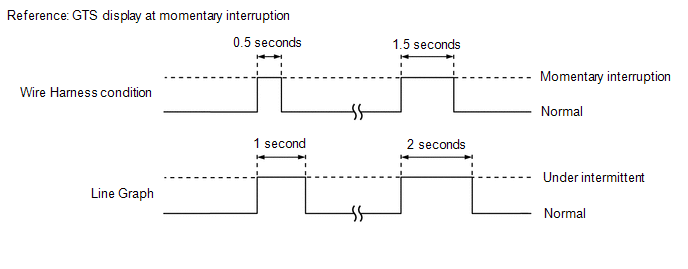
- If the display changes, this indicates that there has been a momentary interruption (open circuit) in the connector and/or wire harness. In this case, repair or replace the connectors and/or wire harnesses as one of them is faulty.
DATA LIST (STEERING SENSOR)
NOTICE:
In the table below, the values listed under "Normal Condition" are reference values. Do not depend solely on these reference values when deciding whether a part is faulty or not.
HINT:
Using the GTS to read the Data List allows the values or states of switches, sensors, actuators and other items to be read without removing any parts. This non-intrusive inspection can be very useful because intermittent conditions or signals may be discovered before parts or wiring is disturbed.
(a) Operate the GTS to read the Data List.
Chassis > Steering Angle Sensor > Data List
|
Tester Display |
Measurement Item |
Range |
Normal Condition |
Diagnostic Note |
|---|---|---|---|---|
|
Total Distance Traveled |
Total distance traveled |
Min.: 0 Max.: 16777215 |
- |
- |
|
Total Distance Traveled - Unit |
Total Distance Traveled unit |
km / mile |
- |
- |
ACTIVE TEST
HINT:
Using the GTS to perform Active Tests allows relays, VSVs, actuators and other items to be operated without removing any parts. This non-intrusive functional inspection can be very useful because intermittent operation may be discovered before parts or wiring is disturbed. Performing Active Tests early in troubleshooting is one way to save diagnostic time. Data List information can be displayed while performing Active Tests.
(a) According to the display on the GTS, perform the Active Test.
NOTICE:
- Although the Active Test automatically turns off the actuator after approximately 5 seconds in order to protect the actuator, do not operate the actuator repeatedly without sufficient waiting time in between.
- To protect the solenoids, do not operate the solenoids repeatedly without sufficient waiting time in between.
- Do not depress the brake pedal when only the pressure release solenoids valves are ON.
- Do not operate more than one solenoid at the same time, except for when operating the pressure hold solenoid and pressure release solenoid of the same wheel.
Chassis > Brake Booster > Active Test
|
Tester Display |
Measurement Item |
Control Range |
Restrict Condition |
Diagnostic Note |
|---|---|---|---|---|
|
ECB Solenoid |
Switching solenoid (SSA, SGH) |
Solenoid Start (Activate) Solenoid SSA / SGH |
Vehicle condition:
HINT: To protect actuator and Solenoid(s), this test will continue for 25 seconds. |
|
|
ECB Main Relay |
Main relay |
OFF / ON |
Vehicle condition: Vehicle stopped HINT: To protect this Actuator and Solenoid, this test will only last 5 seconds. |
ECB: Electronically Controlled Brake System |
|
ECB Solenoid (SLR) |
Linear solenoid reduction valve (SLR) |
Solenoid Start (Activate) Solenoid SLR (It is possible to set the current) |
Vehicle condition:
|
ECB: Electronically Controlled Brake System |
|
ECB Solenoid (SLA) |
Linear solenoid addition valve (SLA) |
Solenoid Start (Activate) Solenoid SLA (It is possible to set the current) |
Vehicle condition:
|
ECB: Electronically Controlled Brake System |
Chassis > Brake/EPB > Active Test
|
Tester Display |
Measurement Item |
Control Range |
Restrict Condition |
Diagnostic Note |
|---|---|---|---|---|
|
EBS Relay |
Emergency brake signal operation |
Relay Start |
Vehicle condition: Vehicle stopped HINT: To protect this Actuator and Solenoid, this test will only last 5 seconds. |
This item is displayed on the GTS but is not used |
|
ABS Solenoid |
Pressure holding solenoid (SFRH, SFLH, SRRH, SRLH) Pressure reduction solenoid (SFRR, SFLR, SRRR, SRLR) |
Solenoid Start (Activate) Solenoid SFRH / SFLH / SRRH / SRLH / SFRR / SFLR / SRRR / SRLR |
Vehicle condition:
HINT: To protect actuator and Solenoid(s), this test will continue for 25 seconds. |
Check that the GTS display for the solenoid (SRLR, SRLH, SRRR, SRRH, SFLR, SFLH, SFRR or SFRH) changes to ON/OFF during Solenoid Start (Activate) |
|
VSC Solenoid |
Master cylinder cut solenoid (SMF (SM1), SMR (SM2)) |
Solenoid Start (Activate) Solenoid SMF / SMR |
Vehicle condition:
HINT: To protect actuator and Solenoid(s), this test will continue for 25 seconds. |
Check that the GTS display for the solenoid (SM1 or SM2) changes to ON/OFF during Solenoid Start (Activate) |
|
Motor Relay |
ABS motor relay |
OFF / ON |
Vehicle condition: Vehicle stopped HINT: To protect this Actuator and Solenoid, this test will only last 5 seconds. |
Operating sound of motor can be heard |
|
Solenoid Relay |
Solenoid relay |
OFF / ON |
Vehicle condition: Vehicle stopped HINT: To protect this Actuator and Solenoid, this test will only last 5 seconds. |
Perform the Active Test and check that the voltage displayed for the solenoid power supply voltage Data List item changes. |
|
Stop Lamp Relay |
Stop light control relay (Stop light switch assembly) |
OFF / ON |
Vehicle condition: Vehicle stopped HINT: To protect this Actuator and Solenoid, this test will only last 5 seconds. |
With the brake pedal released, check that the stop lights illuminate and the value of Stop Light Relay on the GTS changes to ON when Stop Lamp Relay is ON |
|
|
|