| Last Modified: 01-30-2024 | 6.11:8.1.0 | Doc ID: RM100000001S1QP |
| Model Year Start: 2021 | Model: RAV4 | Prod Date Range: [08/2020 - 10/2022] |
| Title: AUDIO / VIDEO: AUDIO AND VISUAL SYSTEM: Illumination Circuit; 2021 - 2022 MY RAV4 RAV4 HV [08/2020 - 10/2022] | ||
|
Illumination Circuit |
DESCRIPTION
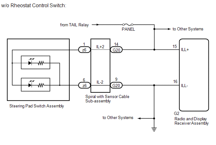
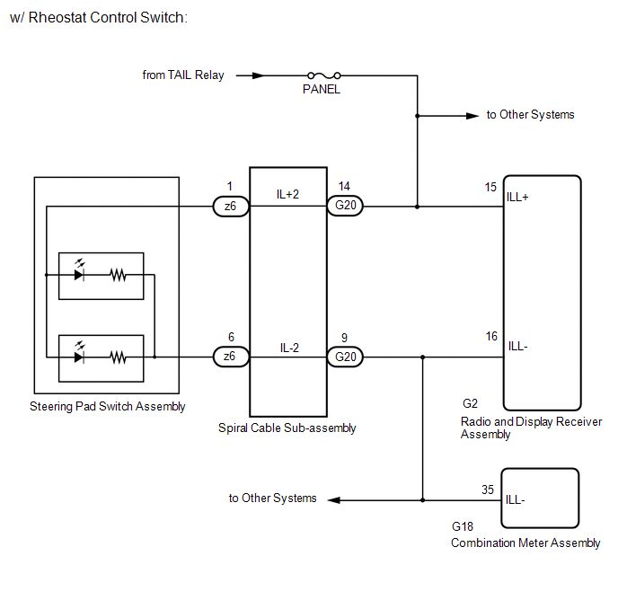
Power is supplied to the radio and display receiver assembly and steering pad switch assembly illumination when the light control switch is in the tail or head position.
WIRING DIAGRAM
CAUTION / NOTICE / HINT
NOTICE:
-
The vehicle is equipped with a Supplemental Restraint System (SRS) which includes components such as airbags. Before servicing (including removal or installation of parts), be sure to read the precaution for Supplemental Restraint System.
Click here
![2021 - 2024 MY RAV4 RAV4 HV [08/2020 - ]; SUPPLEMENTAL RESTRAINT SYSTEMS: AIRBAG SYSTEM: PRECAUTION](/t3Portal/stylegraphics/info.gif)
- Inspect the fuse for circuits related to this system before performing the following procedure.
PROCEDURE
|
1. |
CHECK VEHICLE CONDITION |
(a) Check the vehicle condition.
|
Result |
Proceed to |
|---|---|
|
w/o Rheostat Control Switch |
A |
|
w/ Rheostat Control Switch |
B |
| B |

|
|

|
2. |
CHECK ILLUMINATION |
(a) Check if the illumination for the radio and display receiver assembly, steering pad switch assembly, heater control switch or others (hazard switch, transmission control switch, etc.) comes on when the light control switch is turned to the head or tail position.
|
Result |
Proceed to |
|---|---|
|
Illumination comes on for all components except steering pad switch assembly. |
A |
|
Illumination comes on for all components except radio and display receiver assembly. |
B |
|
No illumination comes on (radio and display receiver assembly, hazard switch, heater control switch, etc.). |
C |
| B |
|
| C |
|
|
|
3. |
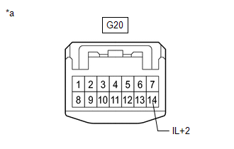
CHECK HARNESS AND CONNECTOR (ILLUMINATION SIGNAL) |
|
(a) Disconnect the spiral cable sub-assembly connector. |
|
(b) Measure the resistance according to the value(s) in the table below.
Standard Resistance:
|
Tester Connection |
Condition |
Specified Condition |
|---|---|---|
|
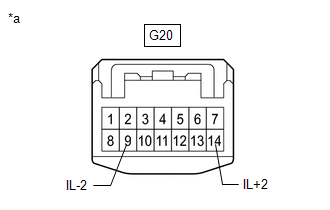
G20-9 (IL-2) - Body ground |
Always |
Below 1 Ω |
(c) Measure the voltage according to the value(s) in the table below.
Standard Voltage:
|
Tester Connection |
Switch Condition |
Specified Condition |
|---|---|---|
|
G20-14 (IL+2) - Body ground |
Light control switch in tail or head position |
11 to 14 V |
| OK |
|
| NG |
|
REPAIR OR REPLACE HARNESS OR CONNECTOR |
|
4. |
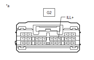
CHECK HARNESS AND CONNECTOR (ILLUMINATION SIGNAL) |
|
(a) Disconnect the radio and display receiver assembly connector. |
|
(b) Measure the voltage according to the value(s) in the table below.
Standard Voltage:
|
Tester Connection |
Switch Condition |
Specified Condition |
|---|---|---|
|
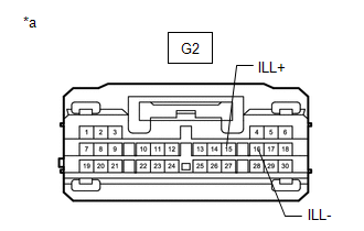
G2-15 (ILL+) - Body ground |
Light control switch in tail or head position |
11 to 14 V |
(c) Measure the resistance according to the value(s) in the table below.
Standard Voltage:
|
Tester Connection |
Condition |
Specified Condition |
|---|---|---|
|
G2-16 (ILL-) - Body ground |
Always |
Below 1 Ω |
| OK |
|
PROCEED TO NEXT SUSPECTED AREA SHOWN IN PROBLEM SYMPTOMS TABLE |
| NG |
|
REPAIR OR REPLACE HARNESS OR CONNECTOR |
|
5. |
CHECK ILLUMINATION |
(a) Check if the illumination for the radio and display receiver assembly, steering pad switch assembly, heater control switch or others (hazard switch, transmission control switch, etc.) comes on when the light control switch is turned to the head or tail position.
|
Result |
Proceed to |
|---|---|
|
Illumination comes on for all components except steering pad switch assembly. |
A |
|
Illumination comes on for all components except radio and display receiver assembly. |
B |
|
No illumination comes on (radio and display receiver assembly, hazard switch, heater control switch, etc.). |
C |
| B |
|
| C |
|
|
|
6. |
CHECK HARNESS AND CONNECTOR (ILLUMINATION SIGNAL) |
|
(a) Disconnect the spiral cable sub-assembly connector. |
|
(b) Measure the voltage according to the value(s) in the table below.
Standard Voltage:
|
Tester Connection |
Switch Condition |
Specified Condition |
|---|---|---|
|
G20-14 (IL+2) - Body ground |
Light control switch in tail or head position |
11 to 14 V |
| NG |
|
REPAIR OR REPLACE HARNESS OR CONNECTOR |
|
|
7. |
INSPECT STEERING PAD SWITCH ASSEMBLY |
(a) Remove the steering pad switch assembly.
Click here
(b) Inspect the steering pad switch assembly.
Click here
| NG |
|
REPLACE STEERING PAD SWITCH ASSEMBLY
|
|
|
8. |
INSPECT SPIRAL CABLE SUB-ASSEMBLY |
(a) Remove the spiral cable sub-assembly.
Click here
(b) Inspect the spiral cable sub-assembly.
Click here
| OK |
|
REPAIR OR REPLACE HARNESS OR CONNECTOR (SPIRAL CABLE SUB-ASSEMBLY - RADIO AND DISPLAY RECEIVER ASSEMBLY, COMBINATION METER ASSEMBLY) |
| NG |
|
REPLACE SPIRAL CABLE SUB-ASSEMBLY
|
|
9. |
CHECK HARNESS AND CONNECTOR (ILLUMINATION SIGNAL) |
|
(a) Disconnect the radio and display receiver assembly connector. |
|
(b) Measure the voltage according to the value(s) in the table below.
Standard Voltage:
|
Tester Connection |
Switch Condition |
Specified Condition |
|---|---|---|
|
G2-15 (ILL+) - Body ground |
Light control switch in tail or head position |
11 to 14 V |
| NG |
|
REPAIR OR REPLACE HARNESS OR CONNECTOR |
|
|
10. |
CHECK HARNESS AND CONNECTOR (RADIO AND DISPLAY RECEIVER ASSEMBLY - COMBINATION METER ASSEMBLY) |
(a) Disconnect the G2 radio and display receiver assembly connector.
(b) Disconnect the G18 combination meter assembly connector.
(c) Measure the resistance according to the value(s) in the table below.
Standard Resistance:
|
Tester Connection |
Condition |
Specified Condition |
|---|---|---|
|
G2-16 (ILL-) - G18-35 (ILL-) |
Always |
Below 1 Ω |
| OK |
|
PROCEED TO NEXT SUSPECTED AREA SHOWN IN PROBLEM SYMPTOMS TABLE |
| NG |
|
REPAIR OR REPLACE HARNESS OR CONNECTOR |
|
|
|