| Last Modified: 01-30-2024 | 6.11:8.1.0 | Doc ID: RM100000001RNJ0 |
| Model Year Start: 2021 | Model: RAV4 | Prod Date Range: [08/2020 - 12/2021] |
| Title: STOP AND START: STOP AND START SYSTEM: Starter Signal Circuit; 2021 MY RAV4 [08/2020 - 12/2021] | ||
|
Starter Signal Circuit |
DESCRIPTION
By using the starter delay circuit, the engine stop and start ECU can activate the ST NO. 2 relay (for starter motor operation) after activating the ST NO. 1 relay (for starter pinion operation) to operate the starter assembly.
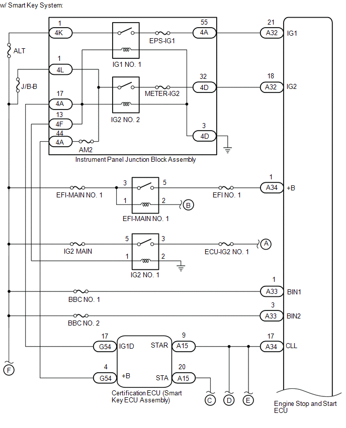
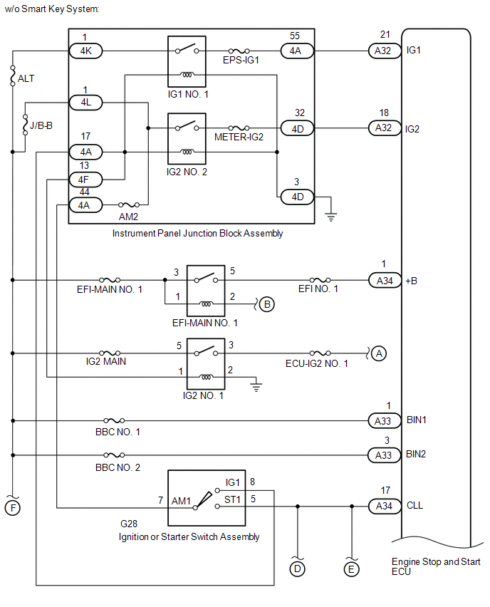
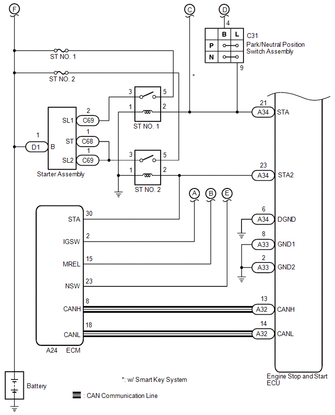
WIRING DIAGRAM
CAUTION / NOTICE / HINT
NOTICE:
-
Before replacing the engine stop and start ECU, read the number of starter operations and write it into a new engine stop and start ECU.
Click here
![2020 - 2021 MY RAV4 [10/2019 - 12/2021]; STOP AND START: STOP AND START SYSTEM: REGISTRATION](/t3Portal/stylegraphics/info.gif)
-
After replacing the engine stop and start ECU or air conditioning amplifier assembly, reset and perform learning of the air conditioning information in the engine stop and start ECU.
Click here
-
After replacing the engine stop and start ECU or airbag ECU assembly, clear and calibrate the deceleration sensor zero point in the engine stop and start ECU.
Click here
-
When the engine stop and start ECU or oil pump with solenoid assembly is replaced, check the oil pump with solenoid assembly.
Click here
-
After replacing the starter assembly, perform initialization of the number of starter operations stored in the engine stop and start ECU.
Click here
- When the starter assembly is replaced, "ST NO. 1 relay" and "ST NO. 2 relay" must be also replaced.
-
After turning ignition switch off, waiting time may be required before disconnecting the cable from the negative (-) battery terminal. Therefore, make sure to read the disconnecting the cable from the negative (-) battery terminal notices before proceeding with work.
Click here
- Inspect the fuses for circuits related to this system before performing the following procedure.
PROCEDURE
|
1. |
CHECK CRANKING |
(a) Turn the ignition switch to START and check that the engine cranks.
|
Result |
Proceed to |
|---|---|
|
Engine cranks |
A |
|
Engine does not crank |
B |
| B |

|
|

|
2. |
PERFORM ACTIVE TEST USING TECHSTREAM (STARTER(HOOD CLOSE)) |
(a) Check that the engine hood is closed.
(b) Connect the Techstream to the DLC3.
(c) Turn the ignition switch to ON.
(d) Turn the Techstream on.
(e) Enter the following menus: Powertrain / Stop and Start / Active Test / Starter(Hood Close).
Powertrain > Stop and Start > Active Test
|
Tester Display |
|---|
|
Starter(Hood Close) |
(f) Check whether the engine cranks while the Active Test "Starter(Hood Close)" is being performed.
NOTICE:
The Active Test "Starter(Hood Close)" is stopped automatically 3 seconds after the starter assembly begins operating.
Standard:
Engine cranks
| OK |
|
|
|
3. |
CHECK HARNESS AND CONNECTOR (BIN1 AND BIN2 TERMINALS POWER SOURCE CIRCUIT) |
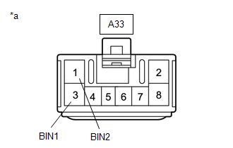
|
*a |
Front view of wire harness connector (to Engine Stop and Start ECU) |
(a) Disconnect the engine stop and start ECU connector.
(b) Measure the voltage according to the value(s) in the table below.
Standard Voltage:
|
Tester Connection |
Condition |
Specified Condition |
|---|---|---|
|
A33-1 (BIN2) - Body ground |
Always |
9.5 to 14 V |
|
A33-3 (BIN1) - Body ground |
Always |
9.5 to 14 V |
| NG |
|
REPAIR OR REPLACE HARNESS OR CONNECTOR (ENGINE STOP AND START ECU - BATTERY) |
|
|
4. |
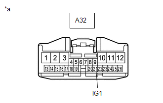
CHECK HARNESS AND CONNECTOR (IG1 TERMINAL POWER SOURCE CIRCUIT) |
|
*a |
Front view of wire harness connector (to Engine Stop and Start ECU) |
(a) Disconnect the engine stop and start ECU connector.
(b) Turn the ignition switch to ON.
(c) Measure the voltage according to the value(s) in the table below.
Standard Voltage:
|
Tester Connection |
Condition |
Specified Condition |
|---|---|---|
|
A32-21 (IG1) - Body ground |
Ignition switch ON |
9.5 to 14 V |
| NG |
|
REPAIR OR REPLACE HARNESS OR CONNECTOR (ENGINE STOP AND START ECU - INSTRUMENT PANEL JUNCTION BLOCK ASSEMBLY (IG1 NO. 1 RELAY)) |
|
|
5. |
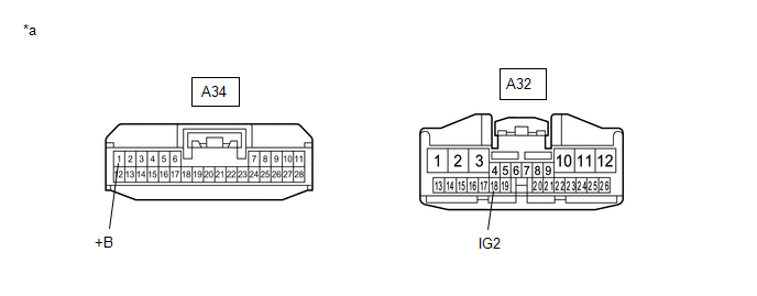
CHECK HARNESS AND CONNECTOR (+B AND IG2 TERMINALS POWER SOURCE CIRCUIT) |
|
*a |
Front view of wire harness connector (to Engine Stop and Start ECU) |
- |
- |
(a) Disconnect the engine stop and start ECU connectors.
(b) Turn the ignition switch to ON.
(c) Measure the voltage according to the value(s) in the table below.
Standard Voltage:
|
Tester Connection |
Condition |
Specified Condition |
|---|---|---|
|
A34-1 (+B) - Body ground |
Ignition switch ON |
9.5 to 14 V |
|
A32-18 (IG2) - Body ground |
Ignition switch ON |
9.5 to 14 V |
| NG |
|
REPAIR OR REPLACE HARNESS OR CONNECTOR (ENGINE STOP AND START ECU - EFI-MAIN NO. 1 RELAY OR INSTRUMENT PANEL JUNCTION BLOCK ASSEMBLY (IG2 NO. 2 RELAY)) |
|
|
6. |
CHECK HARNESS AND CONNECTOR (ENGINE STOP AND START ECU - BODY GROUND) |
(a) Disconnect the engine stop and start ECU connectors.
(b) Measure the resistance according to the value(s) in the table below.
Standard Resistance:
|
Tester Connection |
Condition |
Specified Condition |
|---|---|---|
|
A33-2 (GND2) - Body ground |
Always |
Below 1 Ω |
|
A33-8 (GND1) - Body ground |
Always |
Below 1 Ω |
|
A34-6 (DGND) - Body ground |
Always |
Below 1 Ω |
| OK |
|
| NG |
|
REPAIR OR REPLACE HARNESS OR CONNECTOR |
|
7. |
PERFORM ACTIVE TEST USING TECHSTREAM (STARTER (HOOD CLOSE)) |
(a) Check that the engine hood is closed.
(b) Connect the Techstream to the DLC3.
(c) Turn the ignition switch to ON.
(d) Turn the Techstream on.
(e) Enter the following menus: Powertrain / Stop and Start / Active Test / Starter(Hood Close).
Powertrain > Stop and Start > Active Test
|
Tester Display |
|---|
|
Starter(Hood Close) |
(f) Check whether the engine cranks while the Active Test "Starter(Hood Close)" is being performed.
NOTICE:
The Active Test "Starter(Hood Close)" is stopped automatically 3 seconds after the starter assembly begins operating.
Standard:
Engine cranks
|
Result |
Proceed to |
|---|---|
|
Engine cranks |
A |
|
Engine does not crank |
B |
| B |
|
|
|
8. |
READ VALUE USING TECHSTREAM (NEUTRAL SWITCH) |
(a) Connect the Techstream to the DLC3.
(b) Turn the ignition switch to ON.
(c) Turn the Techstream on.
(d) Enter the following menus: Powertrain / Stop and Start / Data List / Neutral Switch.
Powertrain > Stop and Start > Data List
|
Tester Display |
|---|
|
Neutral Switch |
(e) In accordance with the display on the Techstream, read the Data List.
OK:
|
Techstream Display |
Condition |
Normal Condition |
|---|---|---|
|
Neutral Switch |
Shift lever in P or N |
ON |
|
Shift lever not in P or N |
OFF |
|
Result |
Proceed to |
|---|---|
|
NG |
A |
|
OK (w/ Smart Key System) |
B |
|
OK (w/o Smart Key System) |
C |
| B |
|
| C |
|
|
|
9. |
INSPECT PARK/NEUTRAL POSITION SWITCH ASSEMBLY |
(a) Inspect the park/neutral position switch assembly.
-
for 2WD:
Click here
-
for AWD:
Click here
|
Result |
Proceed to |
|---|---|
|
OK (w/ Smart Key System) |
A |
|
OK (w/o Smart Key System) |
B |
|
NG |
C |
| B |
|
| C |
|
REPLACE PARK/NEUTRAL POSITION SWITCH ASSEMBLY
|
|
|
10. |
CHECK HARNESS AND CONNECTOR (CERTIFICATION ECU (SMART KEY ECU ASSEMBLY) - ST NO. 1 RELAY) |
(a) Disconnect the certification ECU (smart key ECU assembly) connector.
(b) Remove the ST NO. 1 relay from the No. 1 engine room relay block and No. 1 junction block assembly.
(c) Disconnect the engine stop and start ECU connector.
(d) Disconnect the ECM connector.
(e) Measure the resistance according to the value(s) in the table below.
Standard Resistance:
|
Tester Connection |
Condition |
Specified Condition |
|---|---|---|
|
A15-9 (STAR) - 2 (ST NO. 1 relay) |
Shift lever in P or N |
Below 1 Ω |
|
Shift lever not in P or N |
10 kΩ or higher |
| OK |
|
PROCEED TO NEXT SUSPECTED AREA SHOWN IN PROBLEM SYMPTOMS TABLE |
| NG |
|
REPAIR OR REPLACE HARNESS OR CONNECTOR |
|
11. |
CHECK HARNESS AND CONNECTOR (IGNITION OR STARTER SWITCH ASSEMBLY - ST NO. 1 RELAY) |
(a) Disconnect the ignition or starter switch assembly connector.
(b) Remove the ST NO. 1 relay from the No. 1 engine room relay block and No. 1 junction block assembly.
(c) Disconnect the engine stop and start ECU connector.
(d) Disconnect the ECM connector.
(e) Measure the resistance according to the value(s) in the table below.
Standard Resistance:
|
Tester Connection |
Condition |
Specified Condition |
|---|---|---|
|
G28-5 (ST1) - 2 (ST NO. 1 relay) |
Shift lever in P or N |
Below 1 Ω |
|
Shift lever not in P or N |
10 kΩ or higher |
| OK |
|
PROCEED TO NEXT SUSPECTED AREA SHOWN IN PROBLEM SYMPTOMS TABLE |
| NG |
|
REPAIR OR REPLACE HARNESS OR CONNECTOR |
|
12. |
CHECK HARNESS AND CONNECTOR (CERTIFICATION ECU (SMART KEY ECU ASSEMBLY) - PARK/NEUTRAL POSITION SWITCH ASSEMBLY) |
(a) Disconnect the certification ECU (smart key ECU assembly) connector.
(b) Disconnect the park/neutral position switch assembly connector.
(c) Disconnect the engine stop and start ECU connector.
(d) Disconnect the ECM connector.
(e) Measure the resistance according to the value(s) in the table below.
Standard Resistance:
|
Tester Connection |
Condition |
Specified Condition |
|---|---|---|
|
A15-9 (STAR) - C31-4 (B) |
Always |
Below 1 Ω |
|
A15-9 (STAR) or C31-4 (B) - Body ground and other terminals |
Always |
10 kΩ or higher |
| NG |
|
REPAIR OR REPLACE HARNESS OR CONNECTOR |
|
|
13. |
CHECK CERTIFICATION ECU (SMART KEY ECU ASSEMBLY) (STAR SIGNAL) |
|
(a) Disconnect the engine stop and start ECU connector. |
|
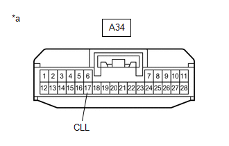
(b) Measure the voltage according to the value(s) in the table below.
Standard Voltage:
|
Tester Connection |
Condition |
Specified Condition |
|---|---|---|
|
A34-17 (CLL) - Body ground |
Engine start |
9.5 to 14 V |
| OK |
|
PROCEED TO NEXT SUSPECTED AREA SHOWN IN PROBLEM SYMPTOMS TABLE |
| NG |
|
|
14. |
INSPECT IGNITION OR STARTER SWITCH ASSEMBLY |
(a) Inspect the ignition or starter switch assembly.
Click here
| NG |
|
|
|
15. |
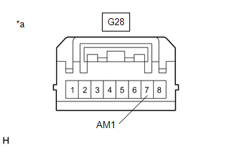
CHECK HARNESS AND CONNECTOR (IGNITION OR STARTER SWITCH ASSEMBLY - BATTERY) |
|
*a |
Front view of wire harness connector (to Ignition or Starter Switch Assembly) |
(a) Disconnect the ignition or starter switch assembly connector.
(b) Measure the voltage according to the value(s) in the table below.
Standard Voltage:
|
Tester Connection |
Condition |
Specified Condition |
|---|---|---|
|
G28-7 (AM1) - Body ground |
Always |
9.5 to 14 V |
| NG |
|
REPAIR OR REPLACE HARNESS OR CONNECTOR |
|
|
16. |
CHECK HARNESS AND CONNECTOR (IGNITION OR STARTER SWITCH ASSEMBLY - PARK/NEUTRAL POSITION SWITCH ASSEMBLY) |
(a) Disconnect the ignition or starter switch assembly connector.
(b) Disconnect the park/neutral position switch assembly connector.
(c) Disconnect the engine stop and start ECU connector.
(d) Disconnect the ECM connector.
(e) Measure the resistance according to the value(s) in the table below.
Standard Resistance:
|
Tester Connection |
Condition |
Specified Condition |
|---|---|---|
|
G28-5 (ST1) - C31-4 (B) |
Always |
Below 1 Ω |
|
G28-5 (ST1) or C31-4 (B) - Body ground and other terminals |
Always |
10 kΩ or higher |
| OK |
|
PROCEED TO NEXT SUSPECTED AREA SHOWN IN PROBLEM SYMPTOMS TABLE |
| NG |
|
REPAIR OR REPLACE HARNESS OR CONNECTOR |
|
17. |
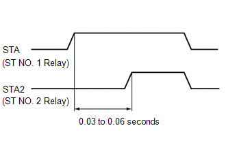
CHECK ENGINE STOP AND START ECU (STA AND STA2 SIGNAL) |
|
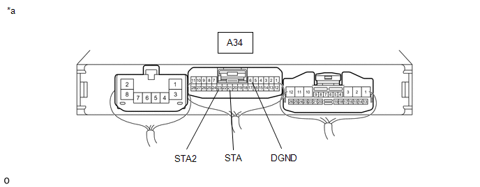
*a |
Component with harness connected (Engine Stop and Start ECU) |
- |
- |
(a) Connect an oscilloscope to the STA, STA2 and DGND terminals of the engine stop and start ECU connector.
|
(b) Check the waveform immediately after turning the ignition switch START.
Result:
NOTICE: After replacing the engine stop and start ECU, make sure that the drive plate and ring gear sub-assembly and starter pinion gear are not excessively worn. A malfunction in the delay circuit may cause the drive plate and ring gear sub-assembly or starter pinion gear to be worn or damaged. |
|
| B |
|
| C |
|
| D |
|
|
|
18. |
INSPECT RELAY (ST NO. 1 RELAY AND ST NO. 2 RELAY) |
(a) Inspect the STNO. 1 relay.
Click here
(b) Inspect the ST NO. 2 relay.
Click here
| NG |
|
REPLACE RELAY (ST NO. 1 RELAY OR ST NO. 2 RELAY) |
|
|
19. |
CHECK HARNESS AND CONNECTOR (ST NO. 1 RELAY AND ST NO. 2 RELAY - BATTERY) |
|
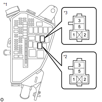
*1 |
No. 1 Engine Room Relay Block and No. 1 Junction Block Assembly |
|
*2 |
ST NO. 1 Relay |
|
*3 |
ST NO. 2 Relay |
(a) Remove the ST NO. 1 relay and ST NO. 2 relay from the No. 1 engine room relay block and No. 1 junction block assembly.
(b) Measure the voltage according to the value(s) in the table below.
Standard Voltage:
|
Tester Connection |
Condition |
Specified Condition |
|---|---|---|
|
5 (ST NO. 1 relay) - Body ground |
Always |
9.5 to 14 V |
|
5 (ST NO. 2 relay) - Body ground |
Always |
9.5 to 14 V |
| NG |
|
REPAIR OR REPLACE HARNESS OR CONNECTOR (ST NO. 1 RELAY OR ST NO. 2 RELAY - BATTERY) |
|
|
20. |
CHECK HARNESS AND CONNECTOR (ST NO. 1 RELAY AND ST NO. 2 RELAY - STARTER ASSEMBLY) |
(a) Remove the ST NO. 1 relay and ST NO. 2 relay from the No. 1 engine room relay block and No. 1 junction block assembly.
(b) Disconnect the starter assembly connector.
(c) Measure the resistance according to the value(s) in the table below.
Standard Resistance:
|
Tester Connection |
Condition |
Specified Condition |
|---|---|---|
|
3 (ST NO. 1 relay) - C69-2 (SL1) |
Always |
Below 1 Ω |
|
3 (ST NO. 2 relay) - C69-1 (SL2) |
Always |
Below 1 Ω |
|
3 (ST NO. 2 relay) - C68-1 (ST) |
Always |
Below 1 Ω |
| NG |
|
REPAIR OR REPLACE HARNESS OR CONNECTOR (ST NO. 1 RELAY OR ST NO. 2 RELAY - STARTER ASSEMBLY) |
|
|
21. |
CHECK HARNESS AND CONNECTOR (ST NO. 1 RELAY AND ST NO. 2 RELAY - BODY GROUND) |
(a) Remove the ST NO. 1 relay and ST NO. 2 relay from the No. 1 engine room relay block and No. 1 junction block assembly.
(b) Measure the resistance according to the value(s) in the table below.
Standard Resistance:
|
Tester Connection |
Condition |
Specified Condition |
|---|---|---|
|
1 (ST NO. 1 relay) - Body ground |
Always |
Below 1 Ω |
|
1 (ST NO. 2 relay) - Body ground |
Always |
Below 1 Ω |
| NG |
|
REPAIR OR REPLACE HARNESS OR CONNECTOR (ST NO. 1 RELAY OR ST NO. 2 RELAY - BODY GROUND) |
|
|
22. |
CHECK HARNESS AND CONNECTOR (ENGINE STOP AND START ECU - ST NO. 1 RELAY) |
(a) Disconnect the engine stop and start ECU connector.
(b) Remove the ST NO. 1 relay from the No. 1 engine room relay block and No. 1 junction block assembly.
(c) Disconnect the certification ECU (smart key ECU assembly) connector. (w/ Smart Key System)
(d) Disconnect the park/neutral position switch assembly connector.
(e) Measure the resistance according to the value(s) in the table below.
Standard Resistance:
|
Tester Connection |
Condition |
Specified Condition |
|---|---|---|
|
A34-21 (STA) - 2 (ST NO. 1 relay) |
Always |
Below 1 Ω |
|
A34-21 (STA) or 2 (ST NO. 1 relay) - Body ground and other terminals |
Always |
10 kΩ or higher |
| NG |
|
REPAIR OR REPLACE HARNESS OR CONNECTOR |
|
|
23. |
CHECK HARNESS AND CONNECTOR (ENGINE STOP AND START ECU - ST NO. 2 RELAY) |
(a) Disconnect the engine stop and start ECU connector.
(b) Remove the ST NO. 2 relay from the No. 1 engine room relay block and No. 1 junction block assembly.
(c) Disconnect the ECM connector.
(d) Measure the resistance according to the value(s) in the table below.
Standard Resistance:
|
Tester Connection |
Condition |
Specified Condition |
|---|---|---|
|
A34-23 (STA2) - 2 (ST NO. 2 relay) |
Always |
Below 1 Ω |
|
A34-23 (STA2) or 2 (ST NO. 2 relay) - Body ground and other terminals |
Always |
10 kΩ or higher |
| NG |
|
REPAIR OR REPLACE HARNESS OR CONNECTOR |
|
|
24. |
CHECK STARTER SIGNAL (OUTPUT WAVEFORM) |
(a) Connect the positive (+) lead of an oscilloscope to the positive (+) battery terminal and the negative (-) lead to the negative (-) battery terminal.
(b) While cranking the engine, count the number of times the waveform drops.
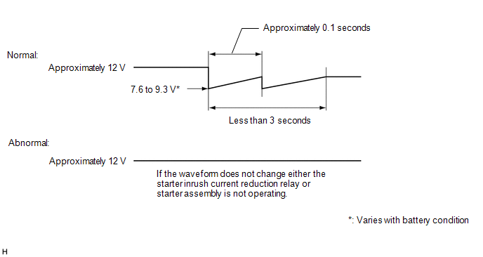
Standard:
Waveform drops 2 times
|
Number of Times Waveform Dropped |
Proceed to |
|---|---|
|
0 times |
A |
|
2 times |
B |
| B |
|
|
|
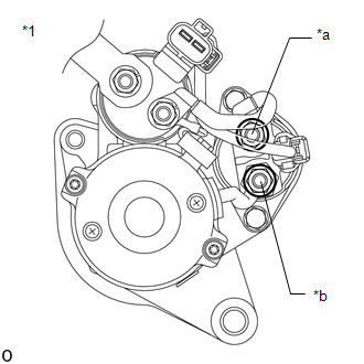
25. |
INSPECT STARTER INRUSH CURRENT REDUCTION RELAY |
|
*1 |
Starter Assembly |
|
*a |
B Terminal |
|
*b |
M Terminal |
(a) Disconnect the cable from the negative (-) battery terminal.
(b) Disconnect terminals B and M of the starter inrush current reduction relay.
(c) Measure the resistance according to the value(s) in the table below.
Standard Resistance:
|
Tester Connection |
Condition |
Specified Condition |
|---|---|---|
|
B Terminal - M Terminal |
Always |
Below 1 Ω |
| NG |
|
|
|
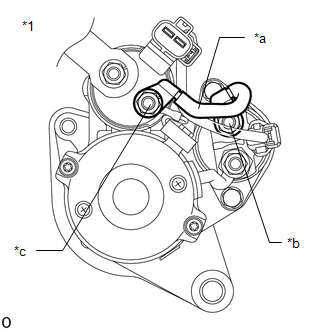
26. |
INSPECT STARTER ASSEMBLY (WIRE HARNESS) |
|
*1 |
Starter Assembly |
|
*a |
Inspect Part |
|
*b |
B Terminal |
|
*c |
C Terminal |
(a) Disconnect the cable from the negative (-) battery terminal.
(b) Disconnect terminal B of the starter inrush current reduction relay.
(c) Disconnect terminal C of the starter assembly.
(d) Measure the resistance according to the value(s) in the table below.
Standard Resistance:
|
Tester Connection |
Condition |
Specified Condition |
|---|---|---|
|
C Terminal - B Terminal |
Always |
Below 1 Ω |
| OK |
|
| NG |
|
REPAIR OR REPLACE WIRE HARNESS |
|
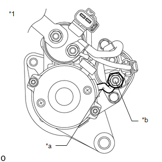
27. |
INSPECT STARTER ASSEMBLY (M TERMINAL) |
|
*1 |
Starter Assembly |
|
*a |
Inspect Part |
|
*b |
M Terminal |
(a) Disconnect the cable from the negative (-) battery terminal.
(b) Disconnect terminal M of the starter inrush current reduction relay.
(c) Measure the resistance according to the value(s) in the table below.
Standard Resistance:
|
Tester Connection |
Condition |
Specified Condition |
|---|---|---|
|
M Terminal - Body ground |
Always |
Below 1 Ω |
| OK |
|
| NG |
|
|
28. |
INSPECT STARTER ASSEMBLY |
(a) Inspect the starter assembly.
Click here
| OK |
|
PROCEED TO NEXT SUSPECTED AREA SHOWN IN PROBLEM SYMPTOMS TABLE |
| NG |
|
|
|
|