| Last Modified: 01-30-2024 | 6.11:8.1.0 | Doc ID: RM100000001R25D |
| Model Year Start: 2021 | Model: RAV4 | Prod Date Range: [08/2020 - ] |
| Title: STEERING COLUMN: STEERING PAD SWITCH: INSPECTION; 2021 - 2024 MY RAV4 RAV4 HV [08/2020 - ] | ||
INSPECTION
PROCEDURE
1. INSPECT STEERING PAD SWITCH ASSEMBLY
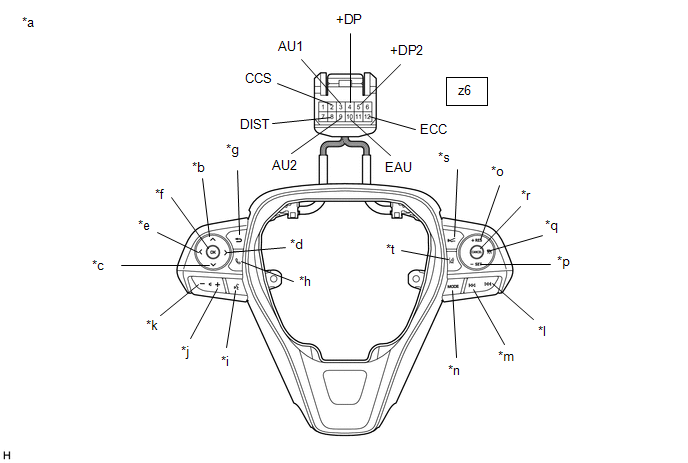
(a) Inspect the steering pad switch assembly.
(1) Measure the resistance according to the value (s) in the table below.
|
*a |
Component without harness connected (Steering Pad Switch Assembly) |
*b |
Up |
|
*c |
Down |
*d |
Right |
|
*e |
Left |
*f |
OK |
|
*g |
Back |
*h |
On/off Hook |
|
*i |
Voice |
*j |
Volume+ |
|
*k |
Volume- |
*l |
Seek+ |
|
*m |
Seek- |
*n |
MODE |
|
*o |
+RES |
*p |
-SET |
|
*q |
Cruise Control Main |
*r |
CANCEL |
|
*s |
Distance Control |
*t |
Lane Departure Alert |
Standard Resistance:
|
Tester Connection |
Condition |
Specified Condition |
|---|---|---|
|
z6-3 (AU1) - z6-10 (EAU) |
No switch pushed |
95 to 105 kΩ |
|
Seek+ switch pushed |
Below 2.5 Ω |
|
|
Seek- switch pushed |
313 to 345 Ω |
|
|
Volume+ switch pushed |
950 to 1050 Ω |
|
|
Volume- switch pushed |
2955 to 3265 Ω |
|
|
z6-9 (AU2) - z6-10 (EAU) |
No switch pushed |
95 to 105 kΩ |
|
MODE switch pushed |
Below 2.5 Ω |
|
|
On/off hook switch pushed |
950 to 1050 Ω |
|
|
Voice switch pushed |
2955 to 3265 Ω |
|
|
z6-5 (+DP2) - z6-10 (EAU) |
No switch pushed |
95 to 105 kΩ |
|
Left switch pushed |
Below 2.5 Ω |
|
|
Up switch pushed |
313 to 345 Ω |
|
|
Down switch pushed |
950 to 1050 Ω |
|
|
Right switch pushed |
2955 to 3265 Ω |
|
|
z6-4 (+DP) - z6-10 (EAU) |
No switch pushed |
95 to 105 kΩ |
|
OK switch pushed |
Below 2.5 Ω |
|
|
Back switch pushed |
313 to 345 Ω |
|
|
z6-8 (DIST) - z6-12 (ECC) |
No switch pushed |
1 MΩ or higher |
|
Distance control switch pushed |
Below 2.5 Ω |
|
|
Lane departure alert switch pushed |
228 to 252 Ω |
|
|
z6-2 (CCS) - z6-12 (ECC) |
No switch pushed |
1 MΩ or higher |
|
Cruise control main switch pushed |
Below 2.5 Ω |
|
|
CANCEL switch pushed |
228 to 252 Ω |
|
|
+RES switch pushed |
599 to 661 Ω |
|
|
-SET switch pushed |
1463 to 1617 Ω |
HINT:
If the result is not as specified, replace the steering pad switch assembly.
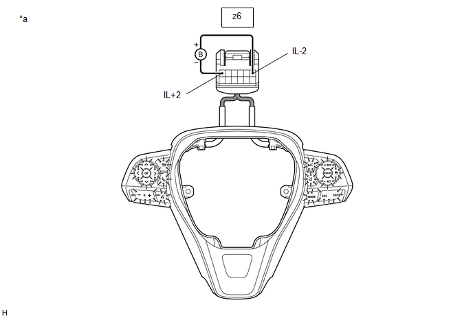
(b) Check the illumination.
|
*a |
Component without harness connected (Steering Pad Switch Assembly) |
- |
- |
(1) Connect a positive (+) lead from the auxiliary battery to terminal z6-1 (IL+2) and a negative (-) lead to terminal z6-6 (IL-2) of the steering pad switch assembly connector.
(2) Check that the steering pad switch assembly illumination illuminates.
OK:
The steering pad switch assembly illumination illuminates.
HINT:
If the result is not as specified, replace the steering pad switch assembly.
|
|
|