|
Last Modified: 01-30-2024 |
6.11:8.1.0 |
Doc ID: RM100000001QT22 |
|
Model Year Start: 2021 |
Model: RAV4 |
Prod Date Range: [08/2020 -
] |
|
Title: DOOR LOCK: WIRELESS DOOR LOCK CONTROL SYSTEM (w/o Smart Key System): TERMINALS OF ECU; 2021 - 2024 MY RAV4 RAV4 HV [08/2020 - ] |
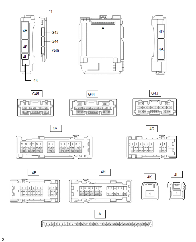
TERMINALS OF ECU
CHECK MAIN BODY ECU (MULTIPLEX NETWORK BODY ECU) AND INSTRUMENT PANEL JUNCTION BLOCK ASSEMBLY
|
*1
|
Main body ECU (multiplex network body ECU)
|
-
|
-
|
(a) Remove the main body ECU (multiplex network body ECU) from the instrument panel junction block assembly.
Click here
![2021 MY RAV4 RAV4 HV [08/2020 - 12/2021]; POWER DISTRIBUTION: MAIN BODY ECU: REMOVAL](/t3Portal/stylegraphics/info.gif)
(b) Reconnect the instrument panel junction block assembly connectors.
(c) Measure the resistance and voltage according to the value(s) in the table below.
HINT:
Measure the values on the wire harness side with the connector disconnected.
|
Terminal No. (Symbol)
|
Wiring Color
|
Input/Output
|
Terminal Description
|
Condition
|
Specified Condition
|
Related Data List Item
|
|
A-11 (GND1) - Body ground
|
-
|
-
|
Ground
|
Always
|
Below 1 Ω
|
-
|
|
A-30 (ACC) - Body ground
|
-
|
Input
|
ACC power supply
|
Ignition switch ACC
|
11 to 14 V
|
ACC SW
|
|
Ignition switch off
|
Below 1 V
|
|
A-31 (BECU) - Body ground
|
-
|
Input
|
Auxiliary battery power supply
|
Ignition switch off
|
11 to 14 V
|
-
|
|
A-32 (IG) - Body ground
|
-
|
Input
|
IG power supply
|
Ignition switch ON
|
11 to 14 V
|
IG SW
|
|
Ignition switch off
|
Below 1 V
|
(d) Install the main body ECU (multiplex network body ECU) to instrument panel junction block assembly.
Click here
(e) Measure the voltage and check for pulses according to the value(s) in the table below.
|
Terminal No. (Symbol)
|
Wiring Color
|
Input/Output
|
Terminal Description
|
Condition
|
Specified Condition
|
Related Data List Item
|
|
G45-11 (PRG) - Body ground
|
B - Body ground
|
Output
|
Output to door control receiver
|
Key inserted into ignition key cylinder → Key pulled out of ignition key cylinder
|
11 to 14 V → Pulse generation → 11 to 14 V
|
-
|
|
G45-10 (RDA) - Body ground
|
R - Body ground
|
Input
|
Input from door control receiver
|
Procedure:
-
Remove key from ignition key cylinder
-
Close all doors
-
Press lock or unlock switch of door control transmitter module set sub-assembly
|
11 to 14 V → Pulse generation
|
-
|
|
4F-29 (BZR) - Body ground
|
L - Body ground
|
Output
|
Wireless door lock buzzer output
|
Active Test Wireless Buzzer on
|
Pulse generation
(frequency: 2 kHz, high voltage: 11 to 14 V, low voltage: below 1 V)
|
-
|
|
Active Test Wireless Buzzer off
|
Below 1 V
|
-
|
|