| Last Modified: 05-08-2025 | 6.11:8.1.0 | Doc ID: RM100000001QOT7 |
| Model Year Start: 2021 | Model: RAV4 | Prod Date Range: [08/2020 - ] |
| Title: A25A-FKS (ENGINE CONTROL): THROTTLE BODY: INSTALLATION; 2021 - 2025 MY RAV4 [08/2020 - ] | ||
INSTALLATION
CAUTION / NOTICE / HINT
NOTICE:
This procedure includes the installation of small-head bolts. Refer to Small-Head Bolts of Basic Repair Hint to identify the small-head bolts.
Click here
![2019 - 2025 MY RAV4 RAV4 HV [11/2018 - ]; INTRODUCTION: REPAIR INSTRUCTION: PRECAUTION](/t3Portal/stylegraphics/info.gif)
HINT:
Perform "Inspection After Repair" after replacing the throttle body with motor assembly.
Click here
PROCEDURE
1. INSTALL THROTTLE BODY WITH MOTOR ASSEMBLY
HINT:
Perform "Inspection After Repair" after replacing the throttle body with motor assembly.
Click here
|
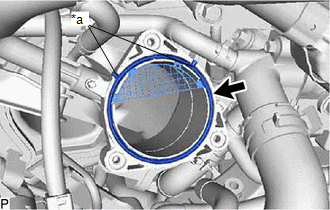
(a) Install a new throttle body gasket to the intake manifold with the protrusions of the throttle body gasket oriented as shown in the illustration. |
|
|
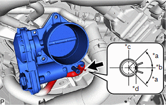
(b) Connect the No. 5 water by-pass hose to the throttle body with motor assembly and slide the clip to secure it. NOTICE:
|
|
|
(c) Install the throttle body with motor assembly to the intake manifold with the 3 bolts. Torque: 10 N·m {102 kgf·cm, 7 ft·lbf} |
|
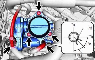
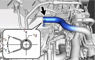
(d) Connect the No. 6 water by-pass hose to the throttle body with motor assembly and slide the clip to secure it.
NOTICE:
Make sure to position the clip as shown in the illustration.
(e) Connect the throttle body with motor assembly connector.
2. INSTALL AIR CLEANER ASSEMBLY WITH AIR CLEANER HOSE
|
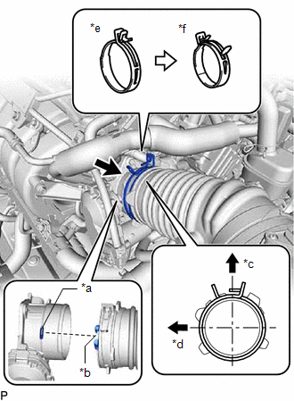
(a) Install the air cleaner assembly with air cleaner hose to the throttle body with motor assembly and unlock the hose clip to secure it as shown in the illustration. NOTICE: Align the cutout of the air cleaner hose with the protrusion of the throttle body with motor assembly. |
|
(b) Insert the air cleaner assembly with air cleaner hose 3 pins into the air cleaner support.
|
(c) Connect the No. 2 PCV hose to the cylinder head cover sub-assembly and slide the clip to secure it. NOTICE: Make sure to position the clip as shown in the illustration. |
|
(d) Connect the vacuum hose to the air cleaner hose.
(e) Attach the 3 wire harness clamps.
(f) Connect the mass air flow meter sub-assembly connector.
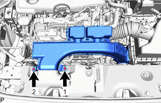
3. INSTALL INLET AIR CLEANER ASSEMBLY
|
(a) Install the inlet air cleaner assembly with the 2 bolts in the order shown in the illustration. Torque: 8.0 N·m {82 kgf·cm, 71 in·lbf} |
|
4. INSTALL NO. 1 ENGINE COVER SUB-ASSEMBLY
Click here
5. ADD ENGINE COOLANT
Click here
6. INSPECT FOR COOLANT LEAK
Click here
|
|
|