| Last Modified: 09-02-2025 | 6.11:8.1.0 | Doc ID: RM100000001QOOM |
| Model Year Start: 2021 | Model: RAV4 | Prod Date Range: [08/2020 - 10/2022] |
| Title: METER / GAUGE / DISPLAY: METER / GAUGE SYSTEM: Steering Pad Switch Circuit; 2021 - 2022 MY RAV4 RAV4 HV [08/2020 - 10/2022] | ||
|
Steering Pad Switch Circuit |
DESCRIPTION
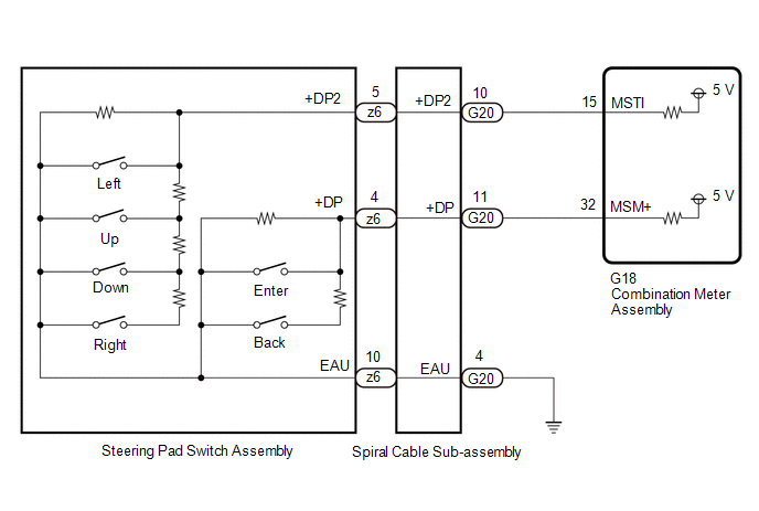
The combination meter assembly and steering pad switch assembly are connected via direct line. The main display and multi-information display in the combination meter assembly are operated using the switches of the steering pad switch assembly.
WIRING DIAGRAM

CAUTION / NOTICE / HINT
NOTICE:
- When replacing the combination meter assembly, always replace it with a new one. If a combination meter assembly which was installed to another vehicle is used, the information stored in it will not match the information from the vehicle and a DTC may be stored.
- The vehicle is equipped with a Supplemental Restraint System (SRS) which includes components such as airbags. Before servicing (including removal or installation of parts), be sure to read the precaution for Supplemental Restraint System.
- After turning the ignition switch off, waiting time may be required before disconnecting the cable from the negative (-) auxiliary battery terminal. Therefore, make sure to read the disconnecting the cable from the negative (-) auxiliary battery terminal notices before proceeding with work.
- When disconnecting the cable from the negative (-) auxiliary battery terminal while performing repairs, some systems need to be initialized after the cable is reconnected.
PROCEDURE
PROCEDURE
|
1. |
READ VALUE USING TECHSTREAM |
(a) Using the Techstream, read the Data List.
Body Electrical > Combination Meter > Data List
|
Tester Display |
Measurement Item |
Range |
Normal Condition |
Diagnostic Note |
|---|---|---|---|---|
|
Multi Switch (Up) |
Steering pad switch assembly (up switch) signal |
OFF or ON |
OFF: Steering pad switch assembly (up switch) released ON: Steering pad switch assembly (up switch) pushed |
- |
|
Multi Switch (Down) |
Steering pad switch assembly (down switch) signal |
OFF or ON |
OFF: Steering pad switch assembly (down switch) released ON: Steering pad switch assembly (down switch) pushed |
- |
|
Multi Switch (Left) |
Steering pad switch assembly (left switch) signal |
OFF or ON |
OFF: Steering pad switch assembly (left switch) released ON: Steering pad switch assembly (left switch) pushed |
- |
|
Multi Switch (Right) |
Steering pad switch assembly (right switch) signal |
OFF or ON |
OFF: Steering pad switch assembly (right switch) released ON: Steering pad switch assembly (right switch) pushed |
- |
|
Multi Switch (Enter) |
Steering pad switch assembly (enter switch) signal |
OFF or ON |
OFF: Steering pad switch assembly (enter switch) released ON: Steering pad switch assembly (enter switch) pushed |
- |
|
Multi Switch (Back) |
Steering pad switch assembly (back switch) signal |
OFF or ON |
OFF: Steering pad switch assembly (back switch) released ON: Steering pad switch assembly (back switch) pushed |
- |
Body Electrical > Combination Meter > Data List
|
Tester Display |
|---|
|
Multi Switch (Up) |
|
Multi Switch (Down) |
|
Multi Switch (Left) |
|
Multi Switch (Right) |
|
Multi Switch (Enter) |
|
Multi Switch (Back) |
OK:
Steering pad switch assembly condition displayed on the Techstream changes with the actual switch operation.
| OK |

|
| NG |

|
|
2. |
INSPECT STEERING PAD SWITCH ASSEMBLY |
(a) Remove the steering pad switch assembly.
(b) Inspect the steering pad switch assembly.
| NG |

|
REPLACE STEERING PAD SWITCH ASSEMBLY |
|
|
3. |
INSPECT SPIRAL CABLE SUB-ASSEMBLY |
(a) Remove the spiral cable sub-assembly.
(b) Inspect the spiral cable sub-assembly.
| NG |

|
REPLACE SPIRAL CABLE SUB-ASSEMBLY |
|
|
4. |
CHECK HARNESS AND CONNECTOR (SPIRAL CABLE SUB-ASSEMBLY - COMBINATION METER ASSEMBLY AND BODY GROUND) |
(a) Disconnect the G20 spiral cable sub-assembly connector.
(b) Disconnect the G18 combination meter assembly connector.
(c) Measure the resistance according to the value(s) in the table below.
Standard Resistance:
|
Tester Connection |
Condition |
Specified Condition |
|---|---|---|
|
G20-10 (+DP2) - G18-15 (MSTI) |
Always |
Below 1 Ω |
|
G20-11 (+DP) - G18-32 (MSM+) |
Always |
Below 1 Ω |
|
G20-4 (EAU) - Body ground |
Always |
Below 1 Ω |
|
G20-10 (+DP2) or G18-15 (MSTI) - Body ground |
Always |
10 kΩ or higher |
|
G20-11 (+DP) or G18-32 (MSM+) - Body ground |
Always |
10 kΩ or higher |
| OK |

|
| NG |

|
REPAIR OR REPLACE HARNESS OR CONNECTOR |
|
|
|
![2021 - 2025 MY RAV4 RAV4 HV [08/2020 - ]; SUPPLEMENTAL RESTRAINT SYSTEMS: AIRBAG SYSTEM: PRECAUTION](/t3Portal/stylegraphics/info.gif)
