- Ignition switch ON
- Steering pad switch assembly operated, "Set Pressure" selected on the multi-information display and "Enter" switch (steering pad switch assembly) pressed and held
| Last Modified: 01-30-2024 | 6.11:8.1.0 | Doc ID: RM100000001QOOB |
| Model Year Start: 2021 | Model: RAV4 | Prod Date Range: [08/2020 - 10/2022] |
| Title: METER / GAUGE / DISPLAY: METER / GAUGE SYSTEM: TERMINALS OF ECU; 2021 - 2022 MY RAV4 RAV4 HV [08/2020 - 10/2022] | ||
TERMINALS OF ECU
COMBINATION METER ASSEMBLY
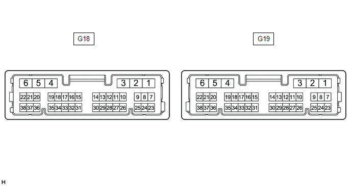
(a) Disconnect the G18 combination meter assembly connector.
(b) Measure the voltage and resistance according to the value(s) in the table below.
|
Terminal No. |
Wiring Color |
Terminal Description |
Condition |
Specified Condition |
|---|---|---|---|---|
|
G18-38 (IG+) - Body ground |
L - Body ground |
IG power supply |
Ignition switch off |
Below 1 V |
|
Ignition switch ON |
11 to 14 V*1 10.5 to 16 V*2 |
|||
|
G18-22 (B) - Body ground |
B - Body ground |
+B power supply |
Ignition switch off |
11 to 14 V |
|
G18-1 (B) - Body ground |
B - Body ground |
+B power supply |
Ignition switch off |
11 to 14 V |
|
G18-35 (ILL-) - Body ground |
L - Body ground |
Illumination signal |
Light control switch off |
Below 1 V |
|
Light control switch in tail or head position |
11 to 14 V |
|||
|
G18-19 (EP) - Body ground |
W-B - Body ground |
Ground |
Always |
Below 1 Ω |
|
G18-23 (ES) - Body ground |
W-B - Body ground |
Ground |
Always |
Below 1 Ω |
- *1: w/o Stop and Start System
- *2: w/ Stop and Start System
(c) Reconnect the G18 combination meter assembly connector.
(d) Measure the voltage and resistance and check for pulses according to the value(s) in the table below.
|
Terminal No. (Symbol) |
Wiring Color |
Terminal Description |
Condition |
Specified Condition |
|---|---|---|---|---|
|
G19-24 (INT) - Body ground*1 |
L - Body ground |
Tire pressure warning light signal |
|
Below 1.5 V |
|
8 to 15 V |
|||
|
G18-20 (SI) - Body ground |
W - Body ground |
Speed signal for other system (Input) |
Ignition switch ON, wheel being rotated |
Pulse generation (See waveform 1) |
|
G18-36 (+S) - Body ground |
L - Body ground |
Speed signal for other system (Output) |
Ignition switch ON, wheel being rotated |
Pulse generation (See waveform 1) |
|
G18-14 (FV) - Body ground |
GR - Body ground |
Fuel sender gauge (Power source) |
Ignition switch ON |
Pulse generation (See waveform 3) |
|
G18-31 (FR) - G18-24 (FE&B) |
LG - BE |
Fuel level signal |
Ignition switch ON, fuel level full → low (fuel level warning light on) |
Pulse generation (See waveform 2) |
|
G18-13 (FR2) - G18-24 (FE&B)*2 |
L - BE |
Fuel level signal |
Ignition switch ON, fuel level full → low (fuel level warning light on) |
Pulse generation (See waveform 2) |
|
G18-24 (FE&B) - Body ground |
BE - Body ground |
Fuel sender gauge (Ground) |
Always |
Below 1 Ω |
|
G19-14 (WLVL) - Body ground |
LG - Body ground |
Washer fluid level signal |
Ignition switch ON, washer fluid level not low |
11 to 14 V |
|
Ignition switch ON, washer fluid level low |
Below 1 V |
|||
|
G19-36 (RLSB) - Body ground*5 |
SB - Body ground |
Rear LH seat belt warning light output signal |
Ignition switch ON, rear seat belt warning light (LH) off |
11 to 14 V |
|
Ignition switch ON, rear seat belt warning light (LH) on |
Below 1 V |
|||
|
G19-19 (RCSB) - Body ground*5 |
B - Body ground |
Rear center seat belt warning light output signal |
Ignition switch ON, rear seat belt warning light (center) off |
11 to 14 V |
|
Ignition switch ON, rear seat belt warning light (center) on |
Below 1 V |
|||
|
G19-35 (RRSB) - Body ground*5 |
LG - Body ground |
Rear RH seat belt warning light output signal |
Ignition switch ON, rear seat belt warning light (RH) off |
11 to 14 V |
|
Ignition switch ON, rear seat belt warning light (RH) on |
Below 1 V |
|||
|
G18-25 (CANL) |
W |
CAN communication line |
- |
- |
|
G18-9 (CANH) |
B |
CAN communication line |
- |
- |
|
G18-10 (MSCL)*4 |
W |
Local bus communication line |
- |
- |
|
G18-27 (MSCH)*4 |
G |
Local bus communication line |
- |
- |
|
G18-15 (MSTI) - Body ground |
R - Body ground |
Steering pad switch signal |
Ignition switch ON, up, down, right and left switches on steering pad switch assembly not pushed |
4.3 to 5.2 V |
|
Ignition switch ON, left switch on steering pad switch pushed |
Below 0.6 V |
|||
|
Ignition switch ON, up switch on steering pad switch pushed |
1.0 to 2.2 V |
|||
|
Ignition switch ON, down switch on steering pad switch pushed |
2.3 to 3.4 V |
|||
|
Ignition switch ON, right switch on steering pad switch pushed |
3.4 to 4.5 V |
|||
|
G18-32 (MSM+) - Body ground |
GR - Body ground |
Steering pad switch signal |
Ignition switch ON, enter and back switches on steering pad switch not pushed |
4.3 to 5.2 V |
|
Ignition switch ON, enter switch on steering pad switch pushed |
Below 0.6 V |
|||
|
Ignition switch ON, back switch on steering pad switch pushed |
1.0 to 2.2 V |
|||
|
G18-34 (SW1) - Body ground |
R - Body ground |
Power source for light control rheostat |
Ignition switch ON |
4.6 to 5.4 V |
|
G18-16 (SW2) - Body ground |
G - Body ground |
Light control rheostat signal |
Light control rheostat fully turned left |
Below 1 Ω |
|
Light control rheostat fully turned right |
8 to 12 kΩ |
|||
|
G18-17 (TC) - Body ground |
B - Body ground |
TAIL cancel switch signal |
TAIL cancel switch on |
Below 1 Ω |
|
TAIL cancel switch off |
1 MΩ or higher |
|||
|
G18-11 (SW3) - Body ground |
B - Body ground |
Light control rheostat ground |
Always |
Below 1 Ω |
|
G19-31 (OILW) - Body ground |
W - Body ground |
Engine oil level signal |
Ignition switch ON, engine oil level not low |
Below 1 V |
|
Ignition switch ON, engine oil level low |
11 to 14 V |
|||
|
G19-7 (LP) - Body ground |
R - Body ground |
Security indicator signal |
Security indicator light off |
Below 2 V |
|
Security indicator light blinking |
Pulse generation |
|||
|
G19-17 (HAZ) - Body ground |
L - Body ground |
Hazard warning signal switch signal (Output) |
Hazard warning signal switch off |
11 to 14 V |
|
Hazard warning signal switch on |
Below 1 V |
|||
|
G19-16 (SW) - Body ground*2 |
G - Body ground |
Brake fluid level signal |
Ignition switch ON, brake fluid level full |
Below 1 V |
|
Ignition switch ON, brake fluid level low (brake fluid level warning light on) |
11 to 14 V |
|||
|
G19-32 (VCM) - Body ground*2 |
BE - Body ground |
Vacuum warning switch signal |
Vacuum warning switch off |
11 to 14 V |
|
Vacuum warning switch on |
Below 1 V |
|||
|
G19-26 (SFT1) - Body ground*6 |
G - Body ground |
Drive mode switch signal (SPORT mode) |
Drive mode switch (SPORT mode) off |
11 to 14 V |
|
Drive mode switch (SPORT mode) on |
Below 1 V |
|||
|
G19-10 (SFT2) - Body ground*6 |
R - Body ground*2 L - Body ground*3 |
Drive mode switch signal (NORMAL mode) |
Drive mode switch (NORMAL mode) off |
11 to 14 V |
|
Drive mode switch (NORMAL mode) on |
Below 1 V |
|||
|
G19-27 (SFT3) - Body ground*6 |
BE - Body ground*2 V - Body ground*3 |
Drive mode switch signal (ECO mode) |
Drive mode switch (ECO mode) off |
11 to 14 V |
|
Drive mode switch (ECO mode) on |
Below 1 V |
|||
|
G19-6 (TRNR) - Body ground |
LA-B - Body ground |
Rear turn signal light RH signal |
Ignition switch ON, RH turn indicator light off |
Below 1 V |
|
Ignition switch ON, RH turn indicator light blinking |
11 to 14 V ←→ Below 1 V |
|||
|
G19-5 (TRNL) - Body ground |
LA-BE - Body ground |
Rear turn signal light LH signal |
Ignition switch ON, LH turn indicator light off |
Below 1 V |
|
Ignition switch ON, LH turn indicator light blinking |
11 to 14 V ←→ Below 1 V |
|||
|
G19-2 (LR) - Body ground |
G - Body ground |
Front/side turn signal light RH signal |
Ignition switch ON, RH turn indicator light off |
Below 1 V |
|
Ignition switch ON, RH turn indicator light blinking |
11 to 14 V ←→ Below 1 V |
|||
|
G19-1 (LL) - Body ground |
L - Body ground |
Front/side turn signal light LH signal |
Ignition switch ON, LH turn indicator light off |
Below 1 V |
|
Ignition switch ON, LH turn indicator light blinking |
11 to 14 V ←→ Below 1 V |
- *1: w/ Tire Pressure Warning System
- *2: for Gasoline Model
- *3: for HV Model
- *4: w/ Audio and Visual System
- *5: w/ Rear Seat Belt Warning Light
- *6: w/ Multi-information Display (for 7 Inch Display)
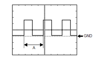
(1) Waveform 1 (Reference):
|
Item |
Condition |
|---|---|
|
Tester connection |
|
|
Tool setting |
5 V/DIV., 20 ms./DIV. |
|
Vehicle condition |
Ignition switch ON, wheel being rotated |
HINT:
When the system is functioning normally, one wheel revolution generates 4 pulses. As the vehicle speed increases, the width indicated by (A) in the illustration narrows.
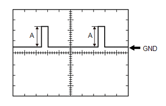
(2) Waveform 2:
|
Item |
Condition |
|---|---|
| *: for Gasoline Model | |
|
Tester connection |
|
|
Tool setting |
2.5 V/DIV., 20 ms./DIV. |
|
Vehicle condition |
Ignition switch ON, fuel level full → low (fuel level warning light on) |
HINT:
(A) will differ depending on the fuel level.
- Fuel level full: 4.2 to 4.6 V
- Fuel level low (fuel level warning light on): 0.3 to 0.7 V
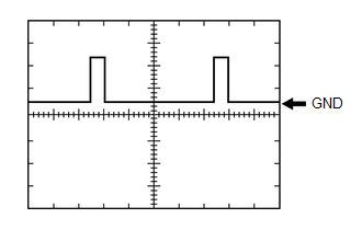
(3) Waveform 3:
|
Item |
Condition |
|---|---|
|
Tester connection |
G18-14 (FV) - Body ground |
|
Tool setting |
2.5 V/DIV., 20 ms./DIV. |
|
Vehicle condition |
Ignition switch ON |
HINT:
Ignition switch ON (4.5 to 5.5 V)
|
|
|