- DTC judgment completed
- System normal
| Last Modified: 01-30-2024 | 6.11:8.1.0 | Doc ID: RM100000001QOKA |
| Model Year Start: 2021 | Model: RAV4 | Prod Date Range: [08/2020 - ] |
| Title: A25A-FKS (ENGINE CONTROL): SFI SYSTEM: P042000; Catalyst System Efficiency Below Threshold Bank 1; 2021 - 2024 MY RAV4 RAV4 HV [08/2020 - ] | ||
|
DTC |
P042000 |
Catalyst System Efficiency Below Threshold Bank 1 |
MONITOR DESCRIPTION
The ECM uses air fuel ratio sensors mounted in front of and behind the Three-Way Catalytic Converter (TWC) to monitor its efficiency.
The first sensor, the air fuel ratio sensor (sensor 1), sends pre-catalyst information to the ECM. The second sensor, the air fuel ratio sensor (sensor 2), sends post-catalyst information to the ECM.
In order to detect any deterioration in the three-way catalytic converter, the ECM calculates the oxygen storage capacity of the three-way catalytic converter. This calculation is based on the output current of the air fuel ratio sensor (sensor 2) while performing active air fuel ratio control.
The oxygen storage capacity value is an indication of the oxygen storage capacity of the three-way catalytic converter. When the vehicle is being driven with a warm engine, active air fuel ratio control is performed for approximately 30 seconds. When it is performed, the ECM deliberately sets the air fuel ratio to lean or rich levels. If the cycle of the waveform for the air fuel ratio sensor (sensor 2) is long, the oxygen storage capacity is great. There is a direct correlation between the air fuel ratio sensor (sensor 2) and the oxygen storage capacity of the three-way catalytic converter.
The ECM uses the oxygen storage capacity value to determine the state of the three-way catalytic converter. If any deterioration has occurred, the ECM will illuminate the MIL and store a DTC.
This system determines the deterioration of the entire catalyst system (including the front and rear catalysts), by using the oxygen storage capacity value of the front catalyst, that is more sensitive than the rear catalyst, as the representative value. Therefore, be sure to replace the front and rear catalysts together when catalyst replacement is necessary.
|
DTC No. |
Detection Item |
DTC Detection Condition |
Trouble Area |
MIL |
Memory |
Note |
|---|---|---|---|---|---|---|
|
P042000 |
Catalyst System Efficiency Below Threshold Bank 1 |
The oxygen storage capacity value is less than the standard value under active air fuel ratio control (1 trip detection logic: except Mexico Models, 2 trip detection logic: for Mexico Models). |
|
Comes on |
DTC stored |
|
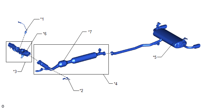
CATALYST LOCATION
|
*1 |
Air Fuel Ratio Sensor (Sensor 1) |
*2 |
Air Fuel Ratio Sensor (Sensor 2) |
|
*3 |
Exhaust Manifold |
*4 |
Front Exhaust Pipe Assembly |
|
*5 |
Tail Exhaust Pipe Assembly |
*6 |
TWC: Front Catalyst |
|
*7 |
TWC: Rear Catalyst |
- |
- |
NOTICE:
When replacing the exhaust manifold (*3) and the front exhaust pipe assembly (*4) in order to replace the three-way catalytic converter, it is not necessary to replace the air fuel ratio sensor (sensor 1) (*1) and the air fuel ratio sensor (sensor 2) (*2).
MONITOR STRATEGY
|
Related DTCs |
P0420: Catalyst deterioration |
|
Required Sensors/Components (Main) |
Air fuel ratio sensor (sensor 1) Air fuel ratio sensor (sensor 2) |
|
Required Sensors/Components (Related) |
Intake air temperature sensor Mass air flow meter sub-assembly Crankshaft position sensor Engine coolant temperature sensor |
|
Frequency of Operation |
Once per driving cycle |
|
Duration |
Approximately 30 seconds |
|
MIL Operation |
2 driving cycles: for Mexico Models Immediate: except Mexico Models |
|
Sequence of Operation |
None |
TYPICAL ENABLING CONDITIONS
|
Monitor runs whenever the following DTCs are not stored |
P0010, P1360, P1362, P1364, P1366, P2614 (Motor drive VVT system control module) P0011 (VVT system - advance) P0012 (VVT system - retard) P0013 (Exhaust VVT oil control solenoid) P0014 (Exhaust VVT system - advance) P0015 (Exhaust VVT system - retard) P0016 (VVT system - misalignment) P0017 (Exhaust VVT system - misalignment) P0031, P0032, P101D (Air fuel ratio sensor (sensor 1) heater) P0037, P0038, P102D (Air fuel ratio sensor (sensor 2) heater) P005D, P014C, P014D, P015A, P015B, P2195, P2196, P2237, P2238, P2239, P2252, P2253 (Air fuel ratio sensor (sensor 1)) P0087, P0088, P0191, P0192, P0193 (Fuel pressure sensor (for high pressure side)) P0101, P0102, P0103 (Mass air flow meter) P0106, P0107, P0108 (Manifold absolute pressure) P0111, P0112, P0113 (Intake air temperature sensor) P0116, P0117, P0118 (Engine coolant temperature sensor) P0121, P0122, P0123, P0222, P0223, P2135 (Throttle position sensor) P0125 (Insufficient coolant temperature for closed loop fuel control) P0128 (Thermostat) P0136, P013A, P2270, P2271, P22AB, P22AC, P22AD, P22B3, P22B4 (Air fuel ratio sensor (sensor 2)) P0171, P0172 (Fuel system) P0201, P0202, P0203, P0204, P062D, P21CF, P21D0, P21D1, P21D2 (Fuel injector) P0300, P0301, P0302, P0303, P0304 (Misfire) P0327, P0328 (Knock control sensor) P0335, P0337, P0338 (Crankshaft position sensor) P0340, P0342, P0343 (Camshaft position sensor) P0365, P0367, P0368 (Exhaust camshaft position sensor) P0400 (EGR system) P0401 (EGR system (closed)) P0489, P0490 (EGR control circuit) P0500 (Vehicle speed sensor) P0657, P0658, P2102, P2103, P2111, P2112, P2119 (Throttle actuator) P107B, P107C, P107D (Fuel pressure sensor (for low pressure side)) P11EA, P11EC, P11ED, P11EE, P11EF, P219A, P219C, P219D, P219E, P219F (Air-fuel ratio imbalance) P1235 (High pressure fuel pump circuit) P2228, P2229 (Atmospheric pressure sensor) |
|
Response rate during fuel cut from rich condition |
Completed |
|
Battery voltage |
11 V or higher |
|
Intake air temperature |
-10°C (14°F) or higher |
|
Engine coolant temperature |
75°C (167°F) or higher |
|
Atmospheric pressure |
76 kPa(abs) [11 psi(abs)] or higher |
|
Idling |
Off |
|
Engine speed |
Less than 3200 rpm |
|
Sub feedback control |
Executing |
|
Air fuel ratio sensor (sensor 1) status |
Activated |
|
Fuel system status |
Closed loop |
|
Engine load |
10% or higher, and less than 100% |
|
All of the following conditions are met |
1, 2 and 3 |
|
1. Mass air flow |
2.5 gm/sec or more, and less than 75 gm/sec |
|
2. Front catalyst temperature (estimated) |
530°C (986°F) or higher, and less than 800°C (1472°F) |
|
3. Rear catalyst temperature (estimated) |
400°C (752°F) or higher, and less than 700°C (1292°F) |
|
Shift position |
3rd or higher |
TYPICAL MALFUNCTION THRESHOLDS
|
Oxygen Storage Capacity (OSC) of catalyst (Normalized) |
Less than 1: except Mexico Models Less than 0.0449: for Mexico Models |
MONITOR RESULT
Refer to detailed information in Checking Monitor Status.
Click here
![2021 - 2024 MY RAV4 RAV4 HV [08/2020 - ]; A25A-FKS (ENGINE CONTROL): SFI SYSTEM: CHECKING MONITOR STATUS](/t3Portal/stylegraphics/info.gif)
P0420: Catalyst Efficiency / O2 STORAGE B1
|
Monitor ID |
Test ID |
Scaling |
Unit |
Description |
|---|---|---|---|---|
|
$21 |
$AF |
Multiply by 0.001 |
No dimension |
Oxygen storage capacity of catalyst bank 1 (Normalization) |
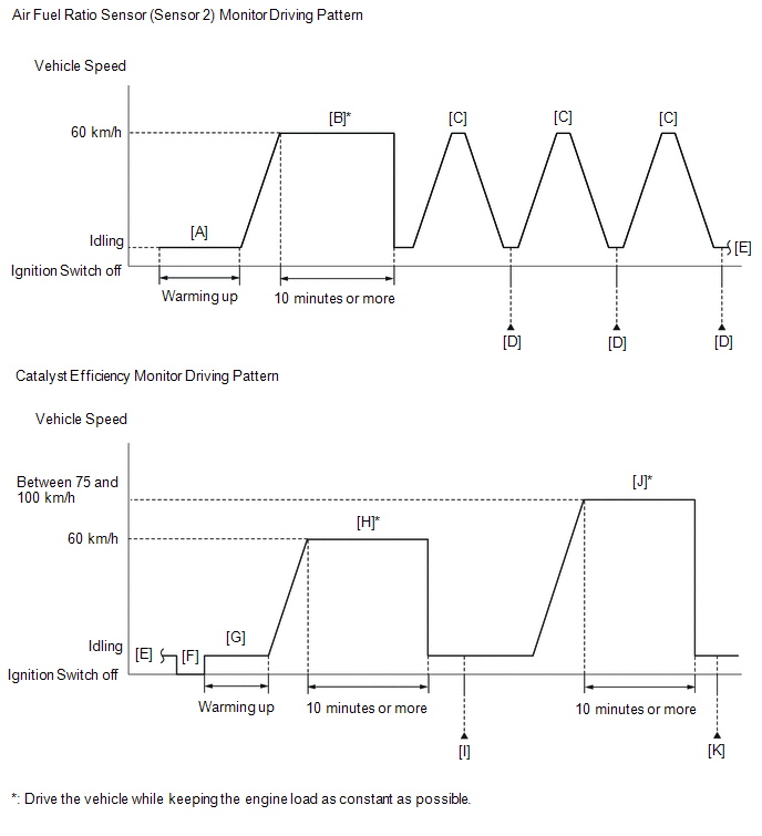
CONFIRMATION DRIVING PATTERN
HINT:
- It is necessary for the response of the air fuel ratio sensor (sensor 2) to be normal in order to confirm DTC P042000. Therefore, perform the confirmation driving pattern for the air fuel ratio sensor (sensor 2) monitor before performing the confirmation driving pattern for the catalyst efficiency monitor.
- Performing this confirmation driving pattern will activate the catalyst efficiency monitor. This is very useful for verifying the completion of a repair.
-
After repair has been completed, clear the DTC and then check that the vehicle has returned to normal by performing the following All Readiness check procedure.
Click here
-
When clearing the permanent DTCs, refer to the "CLEAR PERMANENT DTC" procedure.
Click here
Except Mexico Models
- Connect the Techstream to the DLC3.
- Turn the ignition switch to ON.
- Turn the Techstream on.
- Clear the DTCs (even if no DTCs are stored, perform the clear DTC procedure).
- Turn the ignition switch off and wait for at least 30 seconds.
- Turn the ignition switch to ON.
- Turn the Techstream on.
- Enter the following menus: Powertrain / Engine / Monitor / Current Monitor.
- Check that Catalyst Efficiency / Current is Incomplete.
-
Start the engine and warm it up until the engine coolant temperature is 75°C (167°F) or higher with the shift lever in P [A].
HINT:
In order to keep the idle stable, turn the A/C and all other electric loads off and do not perform any shift operations.
-
Drive the vehicle at approximately 60 km/h (37 mph) for 10 minutes or more [B].
CAUTION:
When performing the confirmation driving pattern, obey all speed limits and traffic laws.
HINT:
Drive the vehicle while keeping the engine load as constant as possible.
-
With the shift lever in S, drive the vehicle at 60 km/h (37 mph), and then decelerate the vehicle by releasing the accelerator pedal for 5 seconds or more to perform the fuel-cut [C].
CAUTION:
When performing the confirmation driving pattern, obey all speed limits and traffic laws.
- Enter the following menus: Powertrain / Engine / Monitor / Current Monitor / O2 Sensor / Details / SLOW RESPONSE B1S2 [D].
-
Check the Test Value for SLOW RESPONSE B1S2.
HINT:
- If Test Value displays a value larger than 0, perform the following procedure, as the O2 Sensor monitor is finished.
- If Test Value displays 0, perform step [C] until it displays a value larger than 0, as the O2 Sensor monitor is not finished.
- Turn the ignition switch off and wait for at least 30 seconds [F].
- Turn the ignition switch to ON.
- Turn the Techstream on.
- Start the engine and warm it up until the engine coolant temperature is 75°C (167°F) or higher [G].
-
Drive the vehicle at approximately 60 km/h (37 mph) for 10 minutes or more [H].
CAUTION:
When performing the confirmation driving pattern, obey all speed limits and traffic laws.
HINT:
- Drive the vehicle while keeping the engine load as constant as possible.
- The monitor item will change to Complete as the Catalyst Efficiency monitor operates.
- Enter the following menus: Powertrain / Engine / Trouble Codes [I].
-
Check if any DTCs are stored.
HINT:
- If the monitor item does not change to Complete, and no DTCs are stored, perform the following procedure.
-
[A] to [I]: Normal judgment procedure.
The normal judgment procedure is used to complete DTC judgment and also used when clearing permanent DTCs.
- When clearing the permanent DTCs, do not disconnect the cable from the battery terminal or attempt to clear the DTCs during this procedure, as doing so will clear the universal trip and normal judgment histories.
-
Drive the vehicle at a speed between 75 and 100 km/h (47 and 62 mph) for 10 minutes or more [J].
CAUTION:
When performing the confirmation driving pattern, obey all speed limits and traffic laws.
HINT:
- Drive the vehicle while keeping the engine load as constant as possible.
- The monitor item will change to Complete as the Catalyst Efficiency monitor operates.
- Enter the following menus: Powertrain / Engine / Trouble Codes [K].
-
Check if any DTCs are stored.
HINT:
If the monitor item does not change to Complete, and no DTCs are stored, extend the driving time.
- Enter the following menus: Powertrain / Engine / Utility / All Readiness.
- Input the DTC: P042000.
-
Check the DTC judgment result.
Techstream Display
Description
NORMAL
ABNORMAL
- DTC judgment completed
- System abnormal
INCOMPLETE
- DTC judgment not completed
- Perform driving pattern after confirming DTC enabling conditions
HINT:
- If the judgment result is NORMAL, the system is normal.
- If the judgment result is ABNORMAL, the system has a malfunction.
-
[A] to [K]: Normal judgment procedure.
The normal judgment procedure is used to complete DTC judgment and also used when clearing permanent DTCs.
- When clearing the permanent DTCs, do not disconnect the cable from the battery terminal or attempt to clear the DTCs during this procedure, as doing so will clear the universal trip and normal judgment histories.
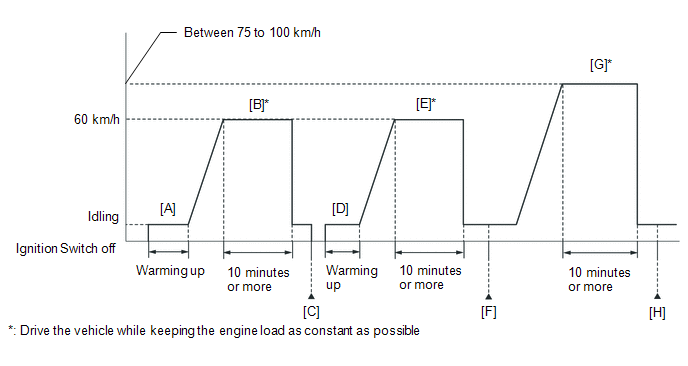
for Mexico Models
HINT:
Performing this confirmation driving pattern will activate the catalyst efficiency monitor. This is very useful for verifying the completion of a repair.
- Connect the Techstream to the DLC3.
- Turn the ignition switch to ON.
- Turn the Techstream on.
- Clear the DTCs (even if no DTCs are stored, perform the clear DTC procedure).
- Turn the ignition switch off and wait for at least 30 seconds.
- Turn the ignition switch to ON and turn the Techstream on.
- Start the engine and warm it up until the engine coolant temperature is 75°C (167°F) or higher [A].
-
Drive the vehicle at approximately 60 km/h (37 mph) for 10 minutes or more [B].
CAUTION:
When performing the confirmation driving pattern, obey all speed limits and traffic laws.
HINT:
Drive the vehicle while keeping the engine load as constant as possible.
- Turn the ignition switch off and wait for at least 30 seconds [C].
- Turn the ignition switch to ON and turn the Techstream on.
- Start the engine and warm it up until the engine coolant temperature is 75°C (167°F) or higher [D].
-
Drive the vehicle at approximately 60 km/h (37 mph) for 10 minutes or more [E].
CAUTION:
When performing the confirmation driving pattern, obey all speed limits and traffic laws.
HINT:
Drive the vehicle while keeping the engine load as constant as possible.
- Enter the following menus: Powertrain / Engine / Trouble Codes [F].
-
Read the pending DTCs.
HINT:
- If a pending DTC is output, the system is malfunctioning.
- If a pending DTC is not output, perform the following procedure.
-
Drive the vehicle at a speed between 75 and 100 km/h (47 and 63 mph) for 10 minutes or more [G].
CAUTION:
When performing the confirmation driving pattern, obey all speed limits and traffic laws.
HINT:
Drive the vehicle while keeping the engine load as constant as possible.
- Enter the following menus: Powertrain / Engine / Utility / All Readiness [H].
- Input the DTC: P042000.
-
Check the DTC judgment result.
Techstream Display
Description
NORMAL
- DTC judgment completed
- System normal
ABNORMAL
- DTC judgment completed
- System abnormal
INCOMPLETE
- DTC judgment not completed
- Perform driving pattern after confirming DTC enabling conditions
HINT:
- If the judgment result shows NORMAL, the system is normal.
- If the judgment result shows ABNORMAL, the system has a malfunction.
-
[A] to [H]: Normal judgment procedure.
The normal judgment procedure is used to complete DTC judgment and also used when clearing permanent DTCs.
- When clearing the permanent DTCs, do not disconnect the cable from the battery terminal or attempt to clear the DTCs during this procedure, as doing so will clear the universal trip and normal judgment histories.
CAUTION / NOTICE / HINT
HINT:
- If a malfunction cannot be found when troubleshooting DTC P042000, a lean or rich abnormality may be the cause. Perform troubleshooting by following the inspection procedure for P017100 (System Too Lean) and P017200 (System Too Rich).
- Sensor 1 refers to the sensor closest to the engine assembly.
- Sensor 2 refers to the sensor farthest away from the engine assembly.
- Read Freeze Frame Data using the Techstream. The ECM records vehicle and driving condition information as Freeze Frame Data the moment a DTC is stored. When troubleshooting, Freeze Frame Data can help determine if the vehicle was moving or stationary, if the engine was warmed up or not, if the air fuel ratio was lean or rich, and other data from the time the malfunction occurred.
PROCEDURE
|
1. |
CHECK ANY OTHER DTCS OUTPUT (IN ADDITION TO DTC P042000) |
(a) Connect the Techstream to the DLC3.
(b) Turn the ignition switch to ON.
(c) Turn the Techstream on.
(d) Enter the following menus: Powertrain / Engine / Trouble Codes.
(e) Read the DTCs.
Powertrain > Engine > Trouble Codes
|
Result |
Proceed to |
|---|---|
|
DTC P042000 is output |
A |
|
DTC P042000 and other DTCs are output |
B |
HINT:
If any DTCs other than P042000 are output, troubleshoot those DTCs first.
| B |

|
GO TO DTC CHART
|
|

|
2. |
READ FREEZE FRAME DATA (LONG FT B1S2) |
(a) Using the GTS, read the value displayed in the Freeze Frame Data.
Powertrain > Engine > DTC(P042000) > Freeze Frame Data
|
Tester Display |
|---|
|
Long FT B1S2 |
|
GTS Display |
Result |
Proceed to |
|---|---|---|
|
Long FT B1S2 |
Less than 1.0% |
A |
|
1.0% or higher |
B |
| B |
|
|
|
3. |
PERFORM ACTIVE TEST USING TECHSTREAM (CONTROL THE INJECTION VOLUME FOR A/F SENSOR) |
(a) Connect the Techstream to the DLC3.
(b) Turn the ignition switch to ON.
(c) Turn the Techstream on.
(d) Start the engine and warm it up until the engine coolant temperature is 75°C (167°F) or higher.
(e) Warm up the air fuel ratio sensors at an engine speed of 2500 rpm for 90 seconds.
(f) Enter the following menus: Powertrain / Engine / Active Test / Control the Injection Volume for A/F Sensor / Data List / Coolant Temperature, A/F (O2) Sensor Current B1S1 and A/F (O2) Sensor Current B1S2.
Powertrain > Engine > Active Test
|
Active Test Display |
|---|
|
Control the Injection Volume for A/F Sensor |
|
Data List Display |
|---|
|
Coolant Temperature |
|
A/F (O2) Sensor Current B1S1 |
|
A/F (O2) Sensor Current B1S2 |
(g) Change the fuel injection volume using the Techstream, and monitor the output current of the air fuel ratio sensor (sensor 1) (A/F (O2) Sensor Current B1S1) and air fuel ratio sensor (sensor 2) (A/F (O2) Sensor Current B1S2) displayed on the Techstream.
HINT:
- The Active Test "Control the Injection Volume for A/F Sensor" can be used to lower the fuel injection volume by 12.5% or increase the injection volume by 12.5%.
- The air fuel ratio sensor (sensor 1) is displayed as A/F (O2) Sensor Current B1S1, and the air fuel ratio sensor (sensor 2) is displayed as A/F (O2) Sensor Current B1S2 on the Techstream.
- The air fuel ratio sensor (sensor 1) has an output delay of a few seconds and the air fuel ratio sensor (sensor 2) has a maximum output delay of approximately 20 seconds.
- If the sensor output current does not change (almost no reaction) while performing the Active Test, the sensor may be malfunctioning.
Standard:
|
Techstream Display (Sensor) |
Injection Volume |
Status |
Current |
|---|---|---|---|
|
A/F (O2) Sensor Current B1S1 (Air fuel ratio (sensor 1)) |
12.5% |
Rich |
Below -0.075 mA |
|
-12.5% |
Lean |
More than 0.037 mA |
|
|
A/F (O2) Sensor Current B1S2 (Air fuel ratio (sensor 2)) |
12.5% |
Rich |
Below -0.86 mA |
|
-12.5% |
Lean |
More than 0.33 mA |
|
Status A/F (O2) Sensor Current B1S1 |
Status A/F (O2) Sensor Current B1S2 |
Actual air fuel ratio, air fuel ratio sensor (sensor 1) and air fuel ratio sensor (sensor 2) condition |
Main Suspected Trouble Area |
Proceed to |
|---|---|---|---|---|
|
Lean/Rich |
Lean/Rich |
Normal |
|
A |
|
Lean |
Lean/Rich |
Air fuel ratio sensor (sensor 1) malfunction |
|
B |
|
Rich |
Lean/Rich |
Air fuel ratio sensor (sensor 1) malfunction |
|
|
|
Lean/Rich |
Lean |
Air fuel ratio sensor (sensor 2) malfunction |
|
C |
|
Lean/Rich |
Rich |
Air fuel ratio sensor (sensor 2) malfunction |
|
|
|
Lean |
Lean |
Actual air fuel ratio lean |
|
D |
|
Rich |
Rich |
Actual air fuel ratio rich |
|
- Lean: During the Control the Injection Volume for A/F Sensor Active Test, the air fuel ratio sensor (sensor 1) output current (A/F (O2) Sensor Current B1S1) is consistently more than 0.037 mA, and the air fuel ratio sensor (sensor 2) output current (A/F (O2) Sensor Current B1S2) is consistently more than 0.33 mA.
- Rich: During the Control the Injection Volume for A/F Sensor Active Test, the air fuel ratio sensor (sensor 1) output current (A/F (O2) Sensor Current B1S1) is consistently below -0.075 mA, and the air fuel ratio sensor (sensor 2) output current (A/F (O2) Sensor Current B1S2) is consistently below -0.86 mA.
- Lean/Rich: During the Control the Injection Volume for A/F Sensor Active Test, the output current of the air fuel ratio sensor (sensor 1) or air fuel ratio sensor (sensor 2) alternate correctly.
HINT:
Refer to "Data List / Active Test" [A/F (O2) Sensor Current B1S1, A/F (O2) Sensor Current B1S2].
Click here
| B |
|
| C |
|
| D |
|
|
|
4. |
CHECK FOR EXHAUST GAS LEAK |
(a) Check for exhaust gas leaks.
OK:
No gas leaks in exhaust system.
| NG |
|
|
|
5. |
PERFORM ACTIVE TEST USING TECHSTREAM (CONTROL THE EGR STEP POSITION) |
(a) Connect the Techstream to the DLC3.
(b) Turn the ignition switch to ON.
(c) Turn the Techstream on.
(d) Start the engine and warm it up until the engine coolant temperature is 75°C (167°F) or higher.
HINT:
The A/C switch and all accessories should be off.
(e) Enter the following menus: Powertrain / Engine / Active Test / Control the EGR Step Position / Data List / Engine Speed, Intake Manifold Absolute Pressure and Coolant Temperature.
Powertrain > Engine > Active Test
|
Active Test Display |
|---|
|
Control the EGR Step Position |
|
Data List Display |
|---|
|
Engine Speed |
|
Intake Manifold Absolute Pressure |
|
Coolant Temperature |
(f) Check the engine idling condition and Intake Manifold Absolute Pressure values in the Data List while performing the Active Test.
NOTICE:
- Do not leave the EGR valve open for 10 seconds or more during the Active Test.
- Be sure to return the EGR valve to step 0 when the Active Test is completed.
- Do not open the EGR valve 30 steps or more during the Active Test.
OK:
The value of Intake Manifold Absolute Pressure and Engine Speed change in response to EGR step position.
Standard:
|
- |
Control the EGR Step Position (Active Test) |
|
|---|---|---|
|
0 Steps |
0 to 30 Steps |
|
|
Idling condition |
Steady idling |
Idling changes from steady to rough idling or engine stalls |
|
Intake Manifold Absolute Pressure (Data List) |
Intake Manifold Absolute Pressure value is 20 to 40 kPa(abs) (2.9 to 5.8 psi(abs)) (EGR valve is fully closed) |
Intake Manifold Absolute Pressure value is at least +10 kPa (1.45 psi) higher than when EGR valve is fully closed |
HINT:
During Active Test, if the idling condition does not change in response to EGR step position, then there is probably a malfunction in the EGR valve.
| OK |
|
|
|
6. |
INSPECT EGR VALVE ASSEMBLY |
(a) Remove the EGR valve assembly.
Click here
(b) Check if the EGR valve is stuck open.
OK:
EGR valve is tightly closed.
HINT:
Perform "Inspection After Repair" after replacing the EGR valve assembly.
Click here
| OK |
|
| NG |
|
REPLACE EGR VALVE ASSEMBLY
|
|
7. |
REPLACE AIR FUEL RATIO SENSOR (SENSOR 1) |
(a) Replace the air fuel ratio sensor (sensor 1).
Click here
HINT:
Perform "Inspection After Repair" after replacing the air fuel ratio sensor (sensor 1).
Click here
| NEXT |
|
|
8. |
CHECK FOR EXHAUST GAS LEAK |
(a) Check for exhaust gas leaks.
OK:
No gas leaks in exhaust system.
| NG |
|
|
|
9. |
REPLACE AIR FUEL RATIO SENSOR (SENSOR 2) |
(a) Replace the air fuel ratio sensor (sensor 2).
Click here
HINT:
Perform "Inspection After Repair" after replacing the air fuel ratio sensor (sensor 2).
Click here
| NEXT |
|
|
10. |
CHECK FOR EXHAUST GAS LEAK |
(a) Check for exhaust gas leaks.
OK:
No gas leaks in exhaust system.
| NG |
|
|
|
11. |
PERFORM ACTIVE TEST USING TECHSTREAM (CONTROL THE EGR STEP POSITION) |
(a) Connect the Techstream to the DLC3.
(b) Turn the ignition switch to ON.
(c) Turn the Techstream on.
(d) Start the engine and warm it up until the engine coolant temperature is 75°C (167°F) or higher.
HINT:
The A/C switch and all accessories should be off.
(e) Enter the following menus: Powertrain / Engine / Active Test / Control the EGR Step Position / Data List / Engine Speed, Intake Manifold Absolute Pressure and Coolant Temperature.
Powertrain > Engine > Active Test
|
Active Test Display |
|---|
|
Control the EGR Step Position |
|
Data List Display |
|---|
|
Engine Speed |
|
Intake Manifold Absolute Pressure |
|
Coolant Temperature |
(f) Check the engine idling condition and Intake Manifold Absolute Pressure values in the Data List while performing the Active Test.
NOTICE:
- Do not leave the EGR valve open for 10 seconds or more during the Active Test.
- Be sure to return the EGR valve to step 0 when the Active Test is completed.
- Do not open the EGR valve 30 steps or more during the Active Test.
OK:
The value of Intake Manifold Absolute Pressure and Engine Speed change in response to EGR step position.
Standard:
|
- |
Control the EGR Step Position (Active Test) |
|
|---|---|---|
|
0 Steps |
0 to 30 Steps |
|
|
Idling condition |
Steady idling |
Idling changes from steady to rough idling or engine stalls |
|
Intake Manifold Absolute Pressure (Data List) |
Intake Manifold Absolute Pressure value is 20 to 40 kPa(abs) (2.9 to 5.8 psi(abs)) (EGR valve is fully closed) |
Intake Manifold Absolute Pressure value is at least +10 kPa (1.45 psi) higher than when EGR valve is fully closed |
HINT:
During Active Test, if the idling condition does not change in response to EGR step position, then there is probably a malfunction in the EGR valve.
| OK |
|
|
|
12. |
INSPECT EGR VALVE ASSEMBLY |
(a) Remove the EGR valve assembly.
Click here
(b) Check if the EGR valve is stuck open.
OK:
EGR valve is tightly closed.
HINT:
Perform "Inspection After Repair" after replacing the EGR valve assembly.
Click here
| NG |
|
REPLACE EGR VALVE ASSEMBLY
|
|
|
13. |
CHECK CAUSE OF EXTREMELY RICH OR LEAN ACTUAL AIR FUEL RATIO |
(a) Check the cause of extremely rich or lean actual air fuel ratio, referring to the DTC P017100 and P017200 Inspection Procedure.
Click here
| NEXT |
|
|
14. |
REPAIR OR REPLACE EXHAUST SYSTEM |
(a) Repair or replace exhaust system.
HINT:
Perform "Inspection After Repair" after repairing or replacing the exhaust system.
Click here
|
|
15. |
CLEAR DTC |
(a) Connect the Techstream to the DLC3.
(b) Turn the ignition switch to ON.
(c) Turn the Techstream on.
(d) Clear the DTCs.
Powertrain > Engine > Clear DTCs
(e) Turn the ignition switch off and wait for at least 30 seconds.
|
|
16. |
CONFIRM WHETHER MALFUNCTION HAS BEEN SUCCESSFULLY REPAIRED |
(a) Drive the vehicle in accordance with the driving pattern described in Confirmation Driving Pattern.
(b) Enter the following menus: Powertrain / Engine / Trouble Codes.
(c) Read the DTCs.
Powertrain > Engine > Trouble Codes
|
Result |
Proceed to |
|---|---|
|
DTCs are not output |
A |
|
DTC P042000 is output |
B |
| A |
|
END |
|
|
17. |
REPLACE EXHAUST MANIFOLD (TWC: FRONT CATALYST) AND FRONT EXHAUST PIPE ASSEMBLY (TWC: REAR CATALYST) |
NOTICE:
When replacing the exhaust manifold and the front exhaust pipe assembly in order to replace the three-way catalytic converter, it is not necessary to replace the air fuel ratio sensor (sensor 1) and the air fuel ratio sensor (sensor 2).
HINT:
Confirm the replacement parts, referring to the illustration in the Catalyst Location.
(a) Replace the exhaust manifold (TWC: Front catalyst).
Click here
(b) Replace the front exhaust pipe assembly (TWC: Rear catalyst).
Click here
| NEXT |
|
END |
|
18. |
CHECK FOR EXHAUST GAS LEAK |
OK:
No gas leaks in exhaust system.
HINT:
Perform "Inspection After Repair" after repairing or replacing the exhaust system.
Click here
| NG |
|
REPAIR OR REPLACE EXHAUST SYSTEM |
|
|
19. |
REPLACE AIR FUEL RATIO SENSOR (SENSOR 2) |
Click here
HINT:
Perform "Inspection After Repair" after replacing the air fuel ratio sensor (sensor 2).
Click here
|
|
20. |
CLEAR DTC |
(a) Clear the DTCs.
Powertrain > Engine > Clear DTCs
(b) Turn the ignition switch off and wait for at least 30 seconds.
|
|
21. |
CONFIRM WHETHER MALFUNCTION HAS BEEN SUCCESSFULLY REPAIRED |
(a) Drive the vehicle in accordance with the driving pattern described in Confirmation Driving Pattern.
(b) Check for DTCs.
Powertrain > Engine > Trouble Codes
DTCs are not output.
| NEXT |
|
END |
|
|
|