- DTC judgment completed
- System normal
| Last Modified: 01-30-2024 | 6.11:8.1.0 | Doc ID: RM100000001QOK7 |
| Model Year Start: 2021 | Model: RAV4 | Prod Date Range: [08/2020 - ] |
| Title: A25A-FKS (ENGINE CONTROL): SFI SYSTEM: P03652A,P036531; Camshaft Position Sensor "B" Bank 1 Signal Stuck in Range; 2021 - 2024 MY RAV4 RAV4 HV [08/2020 - ] | ||
|
DTC |
P03652A |
Camshaft Position Sensor "B" Bank 1 Signal Stuck in Range |
|
DTC |
P036531 |
Camshaft Position Sensor "B" Bank 1 No Signal |
DESCRIPTION
Refer to DTC P036511.
Click here
![2021 - 2024 MY RAV4 RAV4 HV [08/2020 - ]; A25A-FKS (ENGINE CONTROL): SFI SYSTEM: P036511,P036515; Camshaft Position Sensor "B" Bank 1 Circuit Short to Ground+](/t3Portal/stylegraphics/info.gif)
|
DTC No. |
Detection Item |
DTC Detection Condition |
Trouble Area |
MIL |
Memory |
Note |
|---|---|---|---|---|---|---|
|
P03652A |
Camshaft Position Sensor "B" Bank 1 Signal Stuck in Range |
No camshaft position sensor (for exhaust camshaft) signal to ECM while engine cranking (1 trip detection logic). |
|
Comes on |
DTC stored |
|
|
P036531 |
Camshaft Position Sensor "B" Bank 1 No Signal |
No camshaft position sensor (for exhaust camshaft) signal for 5 seconds at an engine speed of 600 rpm or higher (1 trip detection logic). |
|
Comes on |
DTC stored |
|
Reference: Inspection using an oscilloscope.
Click here
MONITOR DESCRIPTION
If no pulse signal is transmitted by the camshaft position sensor (for exhaust camshaft) despite the camshaft rotating, or the rotation of the camshaft and the crankshaft is not synchronized, the ECM interprets this as a malfunction of the sensor.
MONITOR STRATEGY
|
Related DTCs |
P0365: Exhaust camshaft position sensor verify pulse input |
|
Required Sensors/Components (Main) |
Camshaft position sensor (for exhaust camshaft) |
|
Required Sensors/Components (Related) |
Crankshaft position sensor |
|
Frequency of Operation |
Continuous |
|
Duration |
2 times: Case 1 5 seconds: Case 2 |
|
MIL Operation |
Immediate |
|
Sequence of Operation |
None |
TYPICAL ENABLING CONDITIONS
Case 1
|
Monitor runs whenever the following DTCs are not stored |
None |
|
Both of the following conditions are met |
- |
|
Starter |
After off to on timing |
|
Minimum battery voltage while starter on |
Less than 11 V |
Case 2
|
All of the following conditions are met |
- |
|
Engine speed |
600 rpm or higher |
|
Exhaust camshaft position sensor range check fail (P0367, P0368) |
Not detected |
|
Ignition switch |
ON |
|
Starter |
Off |
|
Battery voltage |
8 V or higher |
|
Exhaust camshaft position sensor voltage |
0.3 to 4.7 V |
|
Idling stop control* |
Not operating |
*: w/ Stop and Start System
TYPICAL MALFUNCTION THRESHOLDS
|
Exhaust camshaft position sensor signal |
No signal |
CONFIRMATION DRIVING PATTERN
HINT:
-
After repair has been completed, clear the DTC and then check that the vehicle has returned to normal by performing the following All Readiness check procedure.
Click here
-
When clearing the permanent DTCs, refer to the "CLEAR PERMANENT DTC" procedure.
Click here
- Connect the Techstream to the DLC3.
- Turn the ignition switch to ON.
- Turn the Techstream on.
- Clear the DTCs (even if no DTCs are stored, perform the clear DTC procedure).
- Turn the ignition switch off and wait for at least 30 seconds.
- Start the engine [A].
- Idle the engine for 10 seconds or more [B].
- Turn the Techstream on.
- Enter the following menus: Powertrain / Engine / Trouble Codes [C].
-
Read the pending DTCs.
HINT:
- If a pending DTC is output, the system is malfunctioning.
- If a pending DTC is not output, perform the following procedure.
- Enter the following menus: Powertrain / Engine / Utility / All Readiness.
- Input the DTC: P03652A or P036531.
-
Check the DTC judgment result.
Techstream Display
Description
NORMAL
ABNORMAL
- DTC judgment completed
- System abnormal
INCOMPLETE
- DTC judgment not completed
- Perform driving pattern after confirming DTC enabling conditions
HINT:
- If the judgment result is NORMAL, the system is normal.
- If the judgment result is ABNORMAL, the system is malfunctioning.
- If the judgment result is INCOMPLETE, perform steps [B] through [C] again.
-
[A] to [C]: Normal judgment procedure.
The normal judgment procedure is used to complete DTC judgment and also used when clearing permanent DTCs.
- When clearing the permanent DTCs, do not disconnect the cable from the battery terminal or attempt to clear the DTCs during this procedure, as doing so will clear the universal trip and normal judgment histories.
WIRING DIAGRAM
Refer to DTC P036511.
Click here
CAUTION / NOTICE / HINT
HINT:
- If no problem is found through this diagnostic troubleshooting procedure, there may be a mechanical problem with the engine.
- Read Freeze Frame Data using the Techstream. The ECM records vehicle and driving condition information as Freeze Frame Data the moment a DTC is stored. When troubleshooting, Freeze Frame Data can help determine if the vehicle was moving or stationary, if the engine was warmed up or not, if the air fuel ratio was lean or rich, and other data from the time the malfunction occurred.
PROCEDURE
|
1. |
CHECK HARNESS AND CONNECTOR |
|
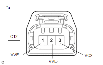
*a |
Front view of wire harness connector (to Camshaft Position Sensor (for Exhaust Camshaft)) |
HINT:
Make sure that the connector is properly connected. If it is not, securely connect it and check for DTCs again.
(a) Disconnect the camshaft position sensor (for exhaust camshaft) connector.
(b) Turn the ignition switch to ON.
(c) Measure the voltage according to the value(s) in the table below.
Standard Voltage:
|
Tester Connection |
Condition |
Specified Condition |
|---|---|---|
|
C12-3 (VC2) - Body ground |
Ignition switch ON |
4.5 to 5.5 V |
|
C12-1 (VVE+) - Body ground |
Ignition switch ON |
3.0 to 5.0 V |
(d) Turn the ignition switch off and wait for at least 30 seconds.
(e) Measure the resistance according to the value(s) in the table below.
Standard Resistance:
|
Tester Connection |
Condition |
Specified Condition |
|---|---|---|
|
C12-3 (VC2) - C12-1 (VVE+) |
Ignition switch off |
1.425 to 1.575 kΩ |
|
C12-2 (VVE-) - Body ground |
Always |
Below 1 Ω |
| NG |

|
|

|
2. |
CHECK SENSOR INSTALLATION AND CONDUCT VISUAL INSPECTION (CAMSHAFT POSITION SENSOR (FOR EXHAUST CAMSHAFT)) |
|
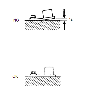
*a |
Clearance |
(a) Visually check the camshaft position sensor (for exhaust camshaft) for damage.
(b) Check the camshaft position sensor (for exhaust camshaft) installation condition.
OK:
The camshaft position sensor (for exhaust camshaft) does not have any damage and is installed properly.
| NG |
|
SECURELY REINSTALL CAMSHAFT POSITION SENSOR (FOR EXHAUST CAMSHAFT) |
|
|
3. |
INSPECT EXHAUST CAMSHAFT (TIMING ROTOR) |
(a) Check the timing rotor of the exhaust camshaft.
OK:
Camshaft timing rotor does not have any cracks or deformation.
HINT:
Perform "Inspection After Repair" after replacing the exhaust camshaft.
Click here
| OK |
|
| NG |
|
|
4. |
CHECK HARNESS AND CONNECTOR (CAMSHAFT POSITION SENSOR (FOR EXHAUST CAMSHAFT) - ECM) |
(a) Disconnect the camshaft position sensor (for exhaust camshaft) connector.
(b) Disconnect the ECM connector.
(c) Measure the resistance according to the value(s) in the table below.
Standard Resistance:
|
Tester Connection |
Condition |
Specified Condition |
|---|---|---|
|
C12-1 (VVE+) - C40-91 (EV1+) |
Always |
Below 1 Ω |
|
C12-2 (VVE-) - C40-114 (EV1-) |
Always |
Below 1 Ω |
|
C12-3 (VC2) - C40-113 (VCE1) |
Always |
Below 1 Ω |
|
C12-1 (VVE+) or C40-91 (EV1+) - Body ground and other terminals |
Always |
10 kΩ or higher |
|
C12-2 (VVE-) or C40-114 (EV1-) - Body ground and other terminals |
Always |
10 kΩ or higher |
|
C12-3 (VC2) or C40-113 (VCE1) - Body ground and other terminals |
Always |
10 kΩ or higher |
| OK |
|
REPLACE ECM
|
| NG |
|
REPAIR OR REPLACE HARNESS OR CONNECTOR |
|
|
|