
- Engine running
- Air conditioning system operating
| Last Modified: 01-30-2024 | 6.11:8.1.0 | Doc ID: RM100000001QM7N |
| Model Year Start: 2021 | Model: RAV4 | Prod Date Range: [08/2020 - ] |
| Title: HEATING / AIR CONDITIONING: AIR CONDITIONING SYSTEM (for Gasoline Model): B14B8; Refrigerant Shortage; 2021 - 2024 MY RAV4 [08/2020 - ] | ||
|
DTC |
B14B8 |
Refrigerant Shortage |
DESCRIPTION
This DTC is stored if the amount of refrigerant in the air conditioning system is insufficient.
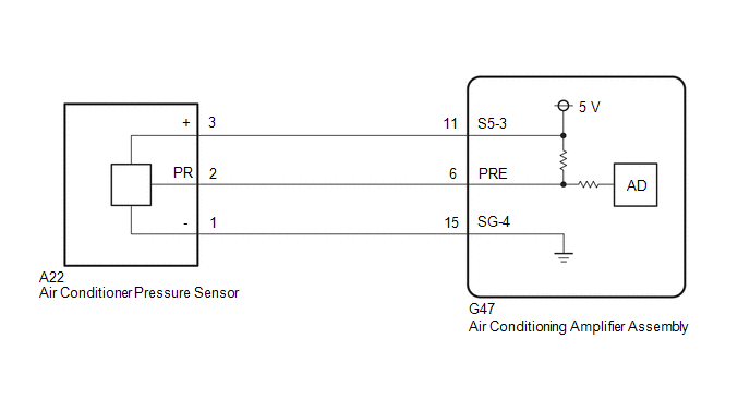
The air conditioning amplifier assembly receives the ambient temperature signal, refrigerant pressure signal, etc. from various sensors.
Based on these signals, the air conditioning amplifier assembly detects the amount of refrigerant.
The A/C switch indicator is turned off and the air conditioning system is stopped if the amount of refrigerant is insufficient.
|
DTC No. |
Detection Item |
DTC Detection Condition |
Trouble Area |
Memory |
|---|---|---|---|---|
|
B14B8 |
Refrigerant Shortage |
|
|
Memorized |
WIRING DIAGRAM
PROCEDURE
|
1. |
CHECK REFRIGERANT PRESSURE |
(a) Connect the Techstream to the DLC3.
(b) Turn the ignition switch to ON.
(c) Turn the Techstream on.
(d) Enter the following menus: Body Electrical / Air Conditioner / Data List.
(e) Read the Data List according to the display on the Techstream.
Body Electrical > Air Conditioner > Data List
|
Tester Display |
Measurement Item |
Range |
Normal Condition |
Diagnostic Note |
|---|---|---|---|---|
|
Regulator Pressure Sensor |
Air conditioner pressure sensor |
Min.: -456.6 kPaG (gauge) Max.: 3294.3 kPaG (gauge) |
Actual refrigerant pressure displayed |
|
Body Electrical > Air Conditioner > Data List
|
Tester Display |
|---|
|
Regulator Pressure Sensor |
(f) Install a manifold gauge set.
Click here
![2019 - 2024 MY RAV4 RAV4 HV [02/2019 - ]; HEATING / AIR CONDITIONING: REFRIGERANT (for HFO-1234yf(R1234yf)): ON-VEHICLE INSPECTION](/t3Portal/stylegraphics/info.gif)
(g) Read the manifold gauge pressure when the following conditions are met.
(1) Prepare the vehicle according to the table below.
Measurement Condition:
|
Item |
Condition |
|---|---|
|
Vehicle Condition |
Engine running |
|
Doors |
Fully closed (windows also fully closed) |
|
A/C Switch |
On |
|
Recirculation/fresh Control Switch |
Recirculation |
|
Set Temperature |
MAX COLD |
|
Blower Speed |
HI |
|
Air Conditioning Air Inlet Temperature |
25 to 35°C (77 to 95°F) |
Standard Pressure:
Low pressure side
150 to 250 kPa (1.5 to 2.5 kgf/cm2, 22 to 36 psi)
High pressure side
1370 to 1570 kPa (14 to 16 kgf/cm2, 199 to 228 psi)
(h) Compare the values displayed in the Data List and on the manifold gauge.
OK:
The values displayed in the Data List and on the manifold gauge match.
| NG |

|
GO TO ON-VEHICLE INSPECTION (CHECK REFRIGERANT PRESSURE USING GAUGE) |
|
|
2. |
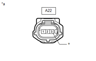
CHECK HARNESS AND CONNECTOR (AIR CONDITIONER PRESSURE SENSOR - POWER SOURCE) |
|
(a) Disconnect the air conditioner pressure sensor connector. |
|
(b) Measure the voltage according to the value(s) in the table below.
Standard Voltage:
|
Tester Connection |
Switch Condition |
Specified Condition |
|---|---|---|
|
A22-3 (+) - Body ground |
Ignition switch ON |
4.75 to 5.25 V |
| NG |
|
|
|
3. |
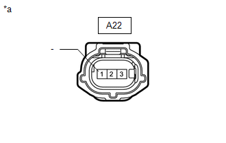
CHECK HARNESS AND CONNECTOR (AIR CONDITIONER PRESSURE SENSOR - BODY GROUND) |
|
(a) Disconnect the air conditioner pressure sensor connector. |
|
(b) Measure the resistance according to the value(s) in the table below.
Standard Resistance:
|
Tester Connection |
Condition |
Specified Condition |
|---|---|---|
|
A22-1 (-) - Body ground |
Always |
Below 1 Ω |
| NG |
|
|
|
4. |
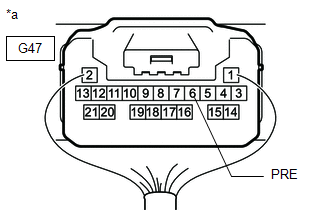
CHECK HARNESS AND CONNECTOR (AIR CONDITIONING AMPLIFIER ASSEMBLY - AIR CONDITIONER PRESSURE SENSOR) |
(a) Disconnect the G47 air conditioning amplifier assembly connector.
(b) Disconnect the A22 air conditioner pressure sensor connector.
(c) Measure the resistance according to the value(s) in the table below.
Standard Resistance:
|
Tester Connection |
Condition |
Specified Condition |
|---|---|---|
|
G47-6 (PRE) - A22-2 (PR) |
Always |
Below 1 Ω |
|
G47-6 (PRE) or A22-2 (PR) - Other terminals and body ground |
Always |
10 kΩ or higher |
| NG |
|
REPAIR OR REPLACE HARNESS OR CONNECTOR |
|
|
5. |
INSPECT AIR CONDITIONING AMPLIFIER ASSEMBLY (SENSOR SIGNAL CIRCUIT) |
(a) Measure the voltage when the following conditions are met.
Measurement Condition:
|
Item |
Condition |
|---|---|
|
Vehicle Condition |
Engine running |
|
Doors |
Fully closed (windows also fully closed) |
|
A/C Switch |
On |
|
Recirculation/fresh Control Switch |
Recirculation |
|
Set Temperature |
MAX COLD |
|
Blower Speed |
HI |
|
Air Conditioning Air Inlet Temperature |
25 to 35°C (77 to 95°F) |
NOTICE:
- If refrigerant pressure on the high pressure side becomes extremely high during the inspection (if the voltage exceeds 4.61 V), the fail-safe function stops compressor operation. Therefore, measure the voltage before the fail-safe operation.
- It is necessary to measure the voltage for a certain amount of time (approximately 10 minutes) because the malfunction may recur after a while.
HINT:
When the outside air temperature is low (below -1.5°C (29.3°F)), the compressor stops due to operation of the thermistor assembly and the No. 1 cooler thermistor to prevent the evaporator from freezing. In this case, perform the inspection in a warm indoor environment.
|
(1) Measure the voltage according to the value(s) in the table below. Standard Voltage:
|
|
(b) Connect the Techstream to the DLC3.
(c) Turn the ignition switch to ON.
(d) Turn the Techstream on.
(e) Enter the following menus: Body Electrical / Air Conditioner / Data List.
(f) Read the Data List according to the display on the Techstream.
Body Electrical > Air Conditioner > Data List
|
Tester Display |
Measurement Item |
Range |
Normal Condition |
Diagnostic Note |
|---|---|---|---|---|
|
Regulator Pressure Sensor |
Air conditioner pressure sensor |
Min.: -456.6 kPaG (gauge) Max.: 3294.3 kPaG (gauge) |
Actual refrigerant pressure displayed |
|
Body Electrical > Air Conditioner > Data List
|
Tester Display |
|---|
|
Regulator Pressure Sensor |
OK:
The voltage and value displayed in the Data List change.
|
Result |
Proceed to |
|---|---|
|
OK |
A |
|
NG (The voltage changes but the value displayed in the Data List does not change.) |
|
|
NG (The voltage does not change.) |
B |
| A |
|
| B |
|
|
6. |
CHECK HARNESS AND CONNECTOR (AIR CONDITIONING AMPLIFIER ASSEMBLY - AIR CONDITIONER PRESSURE SENSOR) |
(a) Disconnect the G47 air conditioning amplifier assembly connector.
(b) Disconnect the A22 air conditioner pressure sensor connector.
(c) Measure the resistance according to the value(s) in the table below.
Standard Resistance:
|
Tester Connection |
Condition |
Specified Condition |
|---|---|---|
|
G47-15 (SG-4) - A22-1 (-) |
Always |
Below 1 Ω |
|
G47-15 (SG-4) or A22-1 (-) - Other terminals and body ground |
Always |
10 kΩ or higher |
| OK |
|
| NG |
|
REPAIR OR REPLACE HARNESS OR CONNECTOR |
|
7. |
CHECK HARNESS AND CONNECTOR (AIR CONDITIONING AMPLIFIER ASSEMBLY - AIR CONDITIONER PRESSURE SENSOR) |
(a) Disconnect the G47 air conditioning amplifier assembly connector.
(b) Disconnect the A22 air conditioner pressure sensor connector.
(c) Measure the resistance according to the value(s) in the table below.
Standard Resistance:
|
Tester Connection |
Condition |
Specified Condition |
|---|---|---|
|
G47-11 (S5-3) - A22-3 (+) |
Always |
Below 1 Ω |
|
G47-11 (S5-3) - A22-3 (+) - Other terminals and body ground |
Always |
10 kΩ or higher |
| OK |
|
| NG |
|
REPAIR OR REPLACE HARNESS OR CONNECTOR |
|
|
|