|
A29-2 (R) - A30-3 (E1)
|
LG - W-B
|
Shift lever position signal
|
Input
|
Ignition switch ON, shift lever in R
|
7.5 to 14 V
|
|
Ignition switch ON, shift lever not in R
|
0 to 1.5 V
|
|
A29-3 (DB1) - A30-3 (E1)
|
W - W-B
|
Shift lever position signal
|
Input
|
Ignition switch ON, shift lever in D or S
|
7.5 to 14 V
|
|
Ignition switch ON, shift lever not in D or S
|
0 to 1.5 V
|
|
A29-4 (HMCH) - A30-3 (E1)
|
B - W-B
|
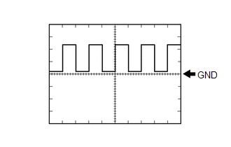
CAN Communication signal
|
Input/Output
|
Ignition switch ON
|
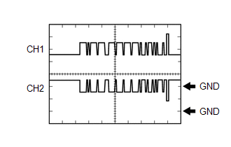
Pulse generation
(Waveform 2)
|
|
A29-5 (MREL) - A30-3 (E1)
|
W - W-B
|
Main relay
|
Output
|
Ignition switch ON
|
11 to 14 V
|
|
A29-6 (HSDN) - A30-3 (E1)
|
G - W-B
|
MG ECU shutdown signal
|
Output
|
Ignition switch ON (READY)
|
0 to 1.5 V
|
|
A29-7 (STP) - A30-3 (E1)
|
G - W-B
|
Stop light switch
|
Input
|
Brake pedal depressed
|
11 to 14 V
|
|
Brake pedal released
|
0 to 1.5 V
|
|
A29-8 (LIN3) - A30-3 (E1)
|
L - W-B
|
LIN communication signal
(A/C inverter, auxiliary battery)
|
Input/Output
|
Ignition switch ON (READY)
|
Pulse generation
|
|
A29-11 (+B1) - A30-3 (E1)
|
R - W-B
|
Power source
|
Input
|
Ignition switch ON
|
11 to 14 V
|
|
A29-14 (HMCL) - A30-3 (E1)
|
W - W-B
|
Communication signal
|
Input/Output
|
Ignition switch ON
|
Pulse generation
(Waveform 2)
|
|
A29-15 (DB2) - A30-3 (E1)
|
P - W-B
|
Shift lever position signal
|
Input
|
Ignition switch ON, shift lever in D or S
|
7.5 to 14 V
|
|
Ignition switch ON, shift lever not in D or S
|
0 to 1.5 V
|
|
A29-16 (PR) - A30-3 (E1)
|
R - W-B
|
Shift lever position signal
|
Input
|
Ignition switch ON, shift lever in P or R
|
7.5 to 14 V
|
|
Ignition switch ON, shift lever not in P or R
|
0 to 1.5 V
|
|
A29-18 (PSFT) - A30-3 (E1)
|
L - W-B
|
Shift lever position sensor power source
|
Output
|
Ignition switch ON (ACC)
|
7.5 to 14 V
|
|
A29-20 (BL) - A30-3 (E1)
|
LA-BE - W-B
|
Back-up light relay
|
Output
|
Ignition switch ON, shift lever in R
|
11 to 14 V
|
|
A29-24 (VCPA) - A29-37 (EPA)
|
R - L
|
Accelerator pedal sensor assembly power source (for VPA)
|
Output
|
Ignition switch ON
|
4.5 to 5.5 V
|
|
A29-26 (VCP2) - A29-25 (EPA2)
|
SB - P
|
Accelerator pedal sensor assembly power source (for VPA2)
|
Output
|
Ignition switch ON
|
4.5 to 5.5 V
|
|
A29-28 (P) - A30-3 (E1)
|
BR - W-B
|
Shift lever position signal
|
Input
|
Ignition switch ON, shift lever in P
|
7.5 to 14 V
|
|
Ignition switch ON, shift lever not in P
|
0 to 1.5 V
|
|
A29-29 (N) - A30-3 (E1)
|
G - W-B
|
Shift lever position signal
|
Input
|
Ignition switch ON, shift lever in N
|
7.5 to 14 V
|
|
Ignition switch ON, shift lever not in N
|
0 to 1.5 V
|
|
A29-30 (PNB) - A30-3 (E1)
|
B - W-B
|
Shift lever position signal
|
Input
|
Ignition switch ON, shift lever in P or N
|
7.5 to 14 V
|
|
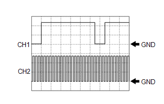
A29-33 (NIWP) - A30-3 (E1)
|
W - W-B
|
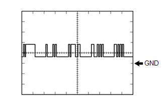
Inverter water pump assembly signal
|
Input
|
Ignition switch ON (READY)
|
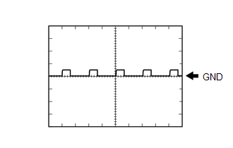
Pulse generation
(Waveform 1)
|
|
A29-34 (IWP) - A30-3 (E1)
|
L - W-B
|
Inverter water pump assembly signal
|
Output
|
Ignition switch ON (READY)
|
Pulse generation
(Waveform 1)
|
|
A29-36 (VPA) - A29-37 (EPA)
|
G - L
|
Accelerator pedal sensor assembly (for accelerator pedal position detection)
|
Input
|
Ignition switch ON, accelerator pedal released
|
0.4 to 1.4 V
|
|
Ignition switch ON, engine stopped, shift lever in P, accelerator pedal fully depressed
|
2.6 to 4.5 V
|
|
A29-38 (VPA2) - A29-25 (EPA2)
|
GR - P
|
Accelerator pedal sensor assembly (for accelerator pedal sensor malfunction detection)
|
Input
|
Ignition switch ON, accelerator pedal released
|
1.0 to 2.2 V
|
|
Ignition switch ON, engine stopped, shift lever in P, accelerator pedal fully depressed
|
3.4 to 5.3 V
|
|
A29-40 (TTA) - A29-39 (ETTA)
|
GR - W
|
Transmission fluid temperature sensor
|
Input
|
Ignition switch ON, temperature 25°C (77°F)
|
3.6 to 4.6 V
|
|
Ignition switch ON, temperature 60°C (140°F)
|
2.2 to 3.2 V
|
|
A29-42 (RMT) - A29-43 (RMTG)
|
L - W
|
Rear motor temperature sensor
|
Input
|
Ignition switch ON, temperature 25°C (77°F)
|
3.6 to 4.6 V
|
|
Ignition switch ON, temperature 60°C (140°F)
|
2.2 to 3.2 V
|
|
A29-46 (MMT) - A29-45 (MMTG)
|
Y - BE
|
Motor temperature sensor
|
Input
|
Ignition switch ON, temperature 25°C (77°F)
|
3.6 to 4.6 V
|
|
Ignition switch ON, temperature 60°C (140°F)
|
2.2 to 3.2 V
|
|
A29-48 (GMT) - A29-47 (GMTG)
|
P - V
|
Generator temperature sensor
|
Input
|
Ignition switch ON, temperature 25°C (77°F)
|
3.6 to 4.6 V
|
|
Ignition switch ON, temperature 60°C (140°F)
|
2.2 to 3.2 V
|
|
A30-1 (+B2) - A30-3 (E1)
|
BE - W-B
|
Power source
|
Input
|
Ignition switch ON
|
11 to 14 V
|
|
A30-4 (ST2) - A30-3 (E1)
|
L - W-B
|
Starter signal
|
Input
|
Ignition switch ON
|
0 to 1.5 V
|
|
A30-7 (INDR) - A30-3 (E1)
|
LG - W-B
|
Shift position indicator signal
|
Input
|
Ignition switch ON, shift lever in R
|
0 to 3.2 V
|
|
Ignition switch ON, shift lever not in R
|
11 to 14 V
|
|
A30-8 (INDD) - A30-3 (E1)
|
W - W-B
|
Shift position indicator signal
|
Input
|
Ignition switch ON, shift lever in D
|
0 to 3.2 V
|
|
Ignition switch ON, shift lever not in D
|
11 to 14 V
|
|
A30-11 (SFTD) - A30-3 (E1)
|
G - W-B
|
Transmission control
|
Input
|
Ignition switch ON, shift lever in S
|
11 to 14 V
|
|
Ignition switch ON, shift lever in (-)
|
0 to 1.5 V
|
|
A30-19 (INDP) - A30-3 (E1)
|
B - W-B
|
Shift position indicator signal
|
Input
|
Ignition switch ON, shift lever in P
|
0 to 3.2 V
|
|
Ignition switch ON, shift lever not in P
|
11 to 14 V
|
|
A30-20 (INDM) - A30-3 (E1)
|
LA-Y - W-B
|
Shift position indicator signal
|
Input
|
Ignition switch ON, shift lever in S
|
0 to 3.2 V
|
|
Ignition switch ON, shift lever not in S
|
11 to 14 V
|
|
A30-21 (INDN) - A30-3 (E1)
|
V - W-B
|
Shift position indicator signal
|
Input
|
Ignition switch ON, shift lever in N
|
0 to 3.2 V
|
|
Ignition switch ON, shift lever not in N
|
11 to 14 V
|
|
A30-24 (SFTU) - A30-3 (E1)
|
Y - W-B
|
Transmission control
|
Input
|
Ignition switch ON, shift lever in S
|
11 to 14 V
|
|
Ignition switch ON, shift lever in (+)
|
0 to 1.5 V
|
|
A30-25 (M) - A30-3 (E1)
|
LA-B - W-B
|
Transmission control
|
Input
|
Ignition switch ON, shift lever in S
|
11 to 14 V
|
|
Ignition switch ON, shift lever not in S
|
0 to 1.5 V
|
|
A30-27 (BATT) - A30-3 (E1)
|
B - W-B
|
Constant power source
|
Input
|
Ignition switch ON
|
11 to 14 V
|
|
Ignition switch ON (READY)
|
11 to 15.5 V
|
|
A30-33 (EVSW) - A30-3 (E1)
|
G - W-B
|
EV mode switch (integration control and panel assembly) signal
|
Input
|
Ignition switch ON, EV mode switch (integration control and panel assembly) not operated
|
11 to 14 V
|
|
Ignition switch ON, EV mode switch (integration control and panel assembly) being pushed and held
|
0 to 1.5 V
|
|
A30-36 (ALSD) - A30-3 (E1)
|
B - W-B
|
TRAIL mode switch (integration control and panel assembly) signal
|
Input
|
Ignition switch ON, TRAIL mode switch (integration control and panel assembly) not operated
|
11 to 14 V
|
|
Ignition switch ON, TRAIL mode switch (integration control and panel assembly) being pushed and held
|
0 to 1.5 V
|
|
A30-37 (SPRT) - A30-3 (E1)
|
R - W-B
|
SPORT mode switch (integration control and panel assembly) signal
|
Input
|
Ignition switch ON, SPORT mode switch (integration control and panel assembly) not turned
|
11 to 14 V
|
|
Ignition switch ON, SPORT mode switch (integration control and panel assembly) being turned and held
|
0 to 1.5 V
|
|
A30-38 (NORM) ←→ A30-3 (E1)
|
SB - W-B
|
NORMAL mode switch (integration control and panel assembly) signal
|
Input
|
Ignition switch ON, NORMAL mode switch (integration control and panel assembly) not operated
|
11 to 14 V
|
|
Ignition switch ON, NORMAL mode switch (integration control and panel assembly) being pushed and held
|
0 to 1.5 V
|
|
A30-44 (IGB) - A30-3 (E1)
|
GR - W-B
|
Power source
|
Input
|
Ignition switch ON
|
11 to 14 V
|
|
A31-5 (ILK) - A30-3 (E1)
|
V - W-B
|
Interlock switch
|
Input
|
Ignition switch ON, service plug grip installed correctly
|
0 to 1.5 V
|
|
Ignition switch ON, service plug grip not installed
|
11 to 14 V
|
|
A31-7 (CA3P) - A30-3 (E1)
|
G - W-B
|
CAN communication signal
|
Input/Output
|
Ignition switch ON
|
Pulse generation
(Waveform 7)
|
|
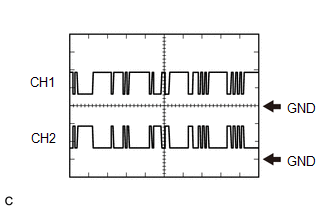
A31-8 (CA1L) - A30-3 (E1)
|
W - W-B
|
CAN communication signal
|
Input/Output
|
Ignition switch ON
|
Pulse generation
(Waveform 5)
|
|
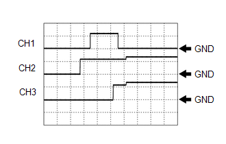
A31-13 (SMRG) - A31-12 (E01)
|
G - W-B
|
System main relay operation signal
|
Output
|
Ignition switch ON → Ignition switch ON (READY)
|
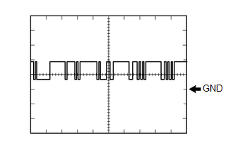
Pulse generation
(Waveform 3)
|
|
A31-15 (SMRP) - A31-12 (E01)
|
W - W-B
|
System main relay operation signal
|
Output
|
Ignition switch ON → Ignition switch ON (READY)
|
Pulse generation
(Waveform 3)
|
|
A31-16 (SMRB) - A31-12 (E01)
|
GR - W-B
|
System main relay operation signal
|
Output
|
Ignition switch ON → Ignition switch ON (READY)
|
Pulse generation
(Waveform 3)
|
|
A31-20 (CA3N) - A30-3 (E1)
|
W - W-B
|
CAN communication signal
|
Input/Output
|
Ignition switch ON
|
Pulse generation
(Waveform 7)
|
|
A31-21 (CA1H) - A30-3 (E1)
|
L - W-B
|
CAN communication signal
|
Input/Output
|
Ignition switch ON
|
Pulse generation
(Waveform 5)
|
|
A31-25 (PLKC) - A30-3 (E1)
|
BE - W-B
|
Shift lock release request signal
|
Output
|
Ignition switch ON (READY), brake pedal depressed
|
11 to 14 V
|
|
Ignition switch ON (READY), brake pedal released
|
0 to 1.5 V
|
|
A31-28 (ST1-) - A30-3 (E1)
|
LA-G - W-B
|
Stop light switch signal
|
Input
|
Ignition switch ON, brake pedal depressed
|
0 to 1.5 V
|
|
Ignition switch ON, brake pedal released
|
11 to 14 V
|
|
A31-29 (ACCI) - A30-3 (E1)
|
P - W-B
|
ACC relay
|
Input
|
Ignition switch ON (ACC)
|
11 to 14 V
|
|
A31-35 (IG2) - A30-3 (E1)
|
B - W-B
|
Power source
|
Input
|
Ignition switch ON
|
11 to 14 V
|
|
A31-38 (SI0) - A30-3 (E1)
|
L - W-B
|
Battery cooling blower operation signal
|
Output
|
Cooling fans operating
|
Pulse generation
(Waveform 6)
|
|
Cooling fans not operating
|
4.5 to 5.5 V
|
|
A31-41 (BTH+) - A30-3 (E1)
|
LG - W-B
|
Communication signal from battery voltage sensor to hybrid vehicle control ECU assembly
|
Input
|
Ignition switch ON
|
Pulse generation
(Waveform 4)
|
|
A31-42 (BTH-) - A30-3 (E1)
|
W - W-B
|
Communication signal from battery voltage sensor to hybrid vehicle control ECU assembly
|
Input
|
Ignition switch ON
|
Pulse generation
(Waveform 4)
|