| Last Modified: 01-30-2024 | 6.11:8.1.0 | Doc ID: RM100000001PAU0 |
| Model Year Start: 2020 | Model: RAV4 HV | Prod Date Range: [06/2020 - ] |
| Title: Q610 (HYBRID TRANSMISSION / TRANSAXLE): REAR TRACTION MOTOR: INSTALLATION; 2020 - 2024 MY RAV4 HV [06/2020 - ] | ||
INSTALLATION
PROCEDURE
1. INSTALL REAR TRACTION MOTOR FILLER PLUG
HINT:
There is no need to remove this unless the rear traction motor filler plug is replaced.
(a) Using a 10 mm hexagon socket wrench, install the rear traction motor filler plug and a new gasket to the rear traction motor with transaxle assembly.
Torque:
39 N·m {398 kgf·cm, 29 ft·lbf}
2. TEMPORARILY INSTALL FRONT DIFFERENTIAL SUPPORT ASSEMBLY
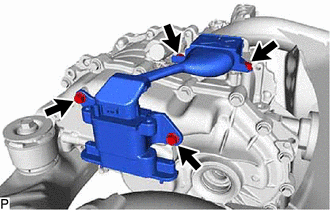
(a) Temporarily install the front differential support assembly to the rear traction motor with transaxle assembly with 2 new bolts.
HINT:
Bolt Length: 55 mm (2.17 in.)
3. INSTALL WIRE HARNESS CLAMP BRACKET
(a) Install the 3 wire harness clamp brackets to the rear traction motor with transaxle assembly with the 4 bolts.
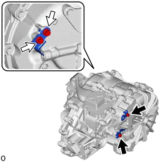

|
Bolt A |

|
Bolt B |
Torque:
for bolt A :
10 N·m {102 kgf·cm, 7 ft·lbf}
for bolt B :
8.0 N·m {82 kgf·cm, 71 in·lbf}
4. INSTALL REAR TRACTION MOTOR WITH TRANSAXLE ASSEMBLY
(a) Using an engine sling device and chain block, hold the rear traction motor with transaxle assembly.
CAUTION:
- Do not lift the rear traction motor with transaxle assembly more than necessary.
- Check the center of gravity while lifting the rear traction motor with transaxle assembly.
NOTICE:
- Do not drop the rear traction motor with transaxle assembly.
- Do not damage the installation surface of the rear traction motor with transaxle assembly.
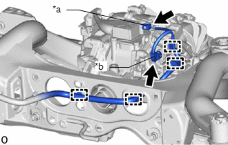
(b) Temporarily install the 2 upper differential mount stoppers and 2 lower differential mount stoppers, rear traction motor with transaxle assembly to the rear suspension member sub-assembly with 3 new bolts.
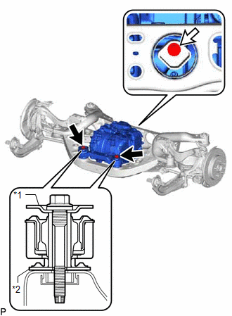
|
*1 |
Upper Differential Mount Stopper |
|
*2 |
Lower Differential Mount Stopper |

|
Bolt A |

|
Bolt B |
|
Bolt |
Bolt Length |
|---|---|
|
A |
110 mm (4.33 in.) |
|
B |
45 mm (1.77 in.) |
(c) Tighten the 5 bolts.
Torque:
for bolt A :
86 N·m {877 kgf·cm, 63 ft·lbf}
for bolt B :
130 N·m {1326 kgf·cm, 96 ft·lbf}
for bolt C :
55 N·m {561 kgf·cm, 41 ft·lbf}
NOTICE:
After tightening bolt B, make sure that the inner cylinder mark and rubber part mark are positioned as shown in the illustration.
HINT:
Tightening order: Tighten bolt (C) → Tighten bolt (B) → Tighten bolt (A)
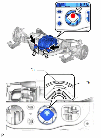
|
*a |
Inner Cylinder Mark |
|
*b |
Rubber Part Mark |

|
Bolt A |

|
Bolt B |

|
Bolt C |
(d) Remove the engine sling device and chain block.
5. INSTALL REAR TRACTION MOTOR CABLE
CAUTION:
Be sure to wear insulated gloves.
NOTICE:
- Protect the rear traction motor cable with a plastic bag or other protective material until immediately before reconnection.
- Do not allow foreign matter or water to enter the rear traction motor cable terminal or installation area.
- Do not touch the rubber seal and terminals of the rear traction motor cable.
HINT:
Unnecessary to remove the rear traction motor cable unless inspection or replacement.
(a) Clean the area around the terminal of the rear traction motor cable, and then blow air on the terminal to remove dust and other foreign matter.
NOTICE:
- Blowing air without cleaning first may cause dust and other foreign matter to enter the terminal.
- Dust or other foreign matter entering the terminal when installing the rear traction motor cable may cause a short or electrical leakage.
|
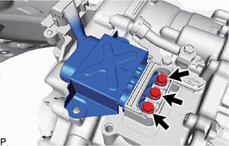
(b) Using an insulated tool, install the rear traction motor cable to the rear traction motor with transaxle assembly with the 3 bolts. Torque: 10 N·m {102 kgf·cm, 7 ft·lbf} |
|
(c) Engage the 2 claws to install a new motor cable terminal cap to the rear traction motor with transaxle assembly.
NOTICE:
- Do not pinch the O-ring.
- Check that the motor cable terminal cap is securely installed.
(d) Slide the cover on the top side of the rear traction motor cable.
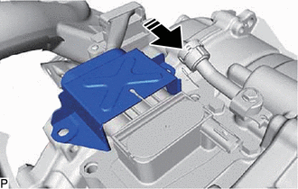

|
Slide cover on top side |
|
(e) Install the 4 bolts of the rear traction motor cable. Torque: 22 N·m {224 kgf·cm, 16 ft·lbf} |
|
6. CONNECT WIRE HARNESS
|
(a) Attach the 4 clamps to connect the wire harness to the rear traction motor with transaxle assembly and rear suspension member sub-assembly. |
|
(b) Connect the resolver sensor connector.
(c) Connect the temperature sensor connector.
7. INSTALL REAR SUSPENSION MEMBER SUB-ASSEMBLY
8. INSTALL REAR DRIVE SHAFT ASSEMBLY
9. ADD HYBRID TRANSAXLE FLUID
10. INSPECT HYBRID TRANSAXLE FLUID
11. INSPECT FOR HYBRID TRANSAXLE FLUID LEAK
12. INSTALL SERVICE PLUG GRIP
13. INSTALL BATTERY SERVICE HOLE COVER
14. CONNECT CABLE TO NEGATIVE AUXILIARY BATTERY TERMINAL
15. INSTALL BATTERY HOLE COVER
16. INSTALL REAR NO. 2 FLOOR BOARD
17. INSTALL DECK BOARD ASSEMBLY
18. PERFORM RESOLVER LEARNING
NOTICE:
If the rear traction motor with transaxle assembly has been replaced, make sure to perform resolver learning.
|
|
|
![2020 - 2021 MY RAV4 HV [06/2020 - 12/2021]; REAR SUSPENSION: REAR SUSPENSION MEMBER (for HV Model AWD): INSTALLATION](/t3Portal/stylegraphics/info.gif)