| Last Modified: 01-30-2024 | 6.11:8.1.0 | Doc ID: RM100000001OR1O |
| Model Year Start: 2020 | Model: RAV4 HV | Prod Date Range: [06/2020 - ] |
| Title: HYBRID / BATTERY CONTROL: MOTOR GENERATOR CONTROL SYSTEM (for LITHIUM-ION BATTERY): P0C5516,P0C5517,P0C5F16,P0C5F17; Drive Motor "B" Position Sensor Circuit "A" Circuit Voltage Below Threshold; 2020 - 2024 MY RAV4 HV [06/2020 - ] | ||
|
DTC |
P0C5516 |
Drive Motor "B" Position Sensor Circuit "A" Circuit Voltage Below Threshold |
|
DTC |
P0C5517 |
Drive Motor "B" Position Sensor Circuit "A" Circuit Voltage Above Threshold |
|
DTC |
P0C5F16 |
Drive Motor "B" Position Sensor Circuit "B" Circuit Voltage Below Threshold |
|
DTC |
P0C5F17 |
Drive Motor "B" Position Sensor Circuit "B" Circuit Voltage Above Threshold |
DTC SUMMARY
MALFUNCTION DESCRIPTION
These DTCs indicate that the resolver output signal is abnormal. The cause of this malfunction may be one of the following:
Internal inverter malfunction
- Inverter with converter assembly internal circuit malfunction
Inverter low-voltage circuit malfunction
- The connectors are not connected properly
HINT:
If any of these DTCs is output, malfunction of the motor generator control ECU circuit board or poor connection of low-voltage connectors is suspected. It is not necessary to inspect the motor resolver.
DESCRIPTION
Refer to the system description for the Rear Motor Resolver Circuit.
Click here
![2020 - 2024 MY RAV4 HV [06/2020 - ]; HYBRID / BATTERY CONTROL: HYBRID CONTROL SYSTEM (for LITHIUM-ION BATTERY): Rear Motor Resolver Circuit](/t3Portal/stylegraphics/info.gif)
|
DTC No. |
Detection Item |
DTC Detection Condition |
Trouble Area |
MIL |
Warning Indicate |
|---|---|---|---|---|---|
|
P0C5516 |
Drive Motor "B" Position Sensor Circuit "A" Circuit Voltage Below Threshold |
The value of the rear motor resolver sin phase signal is lower than the low side threshold. (1 trip detection logic) |
|
Comes on |
Master Warning: Comes on |
|
P0C5517 |
Drive Motor "B" Position Sensor Circuit "A" Circuit Voltage Above Threshold |
The value of the rear motor resolver sin phase signal is higher than the high side threshold. (1 trip detection logic) |
|
Comes on |
Master Warning: Comes on |
|
P0C5F16 |
Drive Motor "B" Position Sensor Circuit "B" Circuit Voltage Below Threshold |
The value of the rear motor resolver cos phase signal is lower than the low side threshold. (1 trip detection logic) |
|
Comes on |
Master Warning: Comes on |
|
P0C5F17 |
Drive Motor "B" Position Sensor Circuit "B" Circuit Voltage Above Threshold |
The value of the rear motor resolver cos phase signal is higher than the high side threshold. (1 trip detection logic) |
|
Comes on |
Master Warning: Comes on |
MONITOR DESCRIPTION
The motor generator control ECU monitors the rear motor resolver output signal. If the motor generator control ECU detects output signals that are out of the normal range or specification, it will conclude that there is a malfunction in the rear motor resolver. If a malfunction is detected, the motor generator control ECU will illuminate the MIL and set a DTC.
MONITOR STRATEGY
|
Related DTCs |
P0C57 (INF P0C5516): Out of range P0C58 (INF P0C5517): Out of range P0C61 (INF P0C5F16): Out of range P0C62 (INF P0C5F17): Out of range |
|
Required sensors/components |
Rear motor resolver |
|
Frequency of operation |
Continuous |
|
Duration |
TMC's intellectual property |
|
MIL operation |
1 driving cycle |
|
Sequence of operation |
None |
TYPICAL ENABLING CONDITIONS
|
The monitor will run whenever the following DTCs are not stored |
TMC's intellectual property |
|
Other conditions belong to TMC's intellectual property |
- |
TYPICAL MALFUNCTION THRESHOLDS
|
TMC's intellectual property |
- |
COMPONENT OPERATING RANGE
|
Motor generator control ECU |
DTC P0C57 (INF P0C5516) is not detected DTC P0C58 (INF P0C5517) is not detected DTC P0C61 (INF P0C5F16) is not detected DTC P0C62 (INF P0C5F17) is not detected |
CONFIRMATION DRIVING PATTERN
HINT:
-
After repair has been completed, clear the DTC and then check that the vehicle has returned to normal by performing the following All Readiness check procedure.
Click here
-
When clearing the permanent DTCs, refer to the "CLEAR PERMANENT DTC" procedure.
Click here
- Connect the Techstream to the DLC3.
- Turn the ignition switch to ON and turn the Techstream on.
- Clear the DTCs (even if no DTCs are stored, perform the clear DTC procedure).
- Turn the ignition switch off and wait for 2 minutes or more.
- Turn the ignition switch to ON and turn the Techstream on.
- With ignition switch ON and wait for 5 seconds or more. [*1]
- Turn the ignition switch to ON (READY) and wait for 5 seconds or more. [*2]
- Depress the accelerator pedal of the vehicle with the engine stopped and the shift lever in P to start the engine. [*3]
- Drive the vehicle forward with the shift lever in D for 5 m (16 ft.) or more. [*4]
-
Drive the vehicle backward with the shift lever in R for 5 m (16 ft.) or more. [*5]
HINT:
[*1] to [*5]: Normal judgment procedure.
The normal judgment procedure is used to complete DTC judgment and also used when clearing permanent DTCs.
- Enter the following menus: Powertrain / Motor Generator / Utility / All Readiness.
-
Check the DTC judgment result.
HINT:
- If the judgment result shows NORMAL, the system is normal.
- If the judgment result shows ABNORMAL, the system has a malfunction.
- If the judgment result shows INCOMPLETE, perform the normal judgment procedure again.
CAUTION / NOTICE / HINT
CAUTION:
-
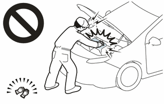
Before the following operations are conducted, take precautions to prevent electric shock by turning the ignition switch off, wearing insulated gloves, and removing the service plug grip from HV battery.
- Inspecting the high-voltage system
- Disconnecting the low voltage connector of the inverter with converter assembly
- Disconnecting the low voltage connector of the HV battery
-
To prevent electric shock, make sure to remove the service plug grip to cut off the high voltage circuit before servicing the vehicle.
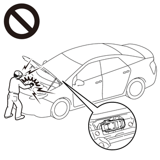
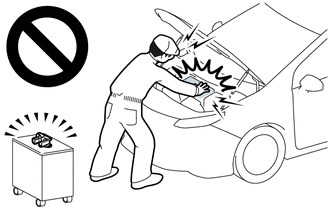
-
After removing the service plug grip from the HV battery, put it in your pocket to prevent other technicians from accidentally reconnecting it while you are working on the high-voltage system.
-
After removing the service plug grip, wait for at least 10 minutes before touching any of the high-voltage connectors or terminals. After waiting for 10 minutes, check the voltage at the terminals in the inspection point in the inverter with converter assembly. The voltage should be 0 V before beginning work.
Click here
HINT:
Waiting for at least 10 minutes is required to discharge the high-voltage capacitor inside the inverter with converter assembly.
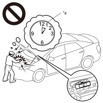
*a
Without waiting for 10 minutes
NOTICE:
After turning the ignition switch off, waiting time may be required before disconnecting the cable from the negative (-) auxiliary battery terminal. Therefore, make sure to read the disconnecting the cable from the negative (-) auxiliary battery terminal notices before proceeding with work.
Click here
HINT:
- If the problem symptom cannot be reproduced, performing a road test on a road on which the vehicle tends to vibrate will make it easier to reproduce the symptom.
- If the resolver is malfunctioning, the vehicle may not drive smoothly.
- When inspecting the connectors, if it is difficult to judge if a connector was disconnected, deformed or improperly secured, disconnect and reconnect the connector and then check for DTCs again. Check if the same DTC is output. If the same DTC is not output, improper connection of connectors is suspected.
- As a malfunction detection threshold may be exceeded when performing the vibration or heat connector inspections, make sure to perform the following inspection to check that the DTC was not stored due to the malfunction of a part.
PROCEDURE
|
1. |
CHECK DTC OUTPUT |
(a) Connect the Techstream to the DLC3.
(b) Turn the ignition switch to ON.
(c) Enter the following menus: Powertrain / Hybrid Control and Motor Generator / Trouble Codes.
(d) Check for DTCs.
Powertrain > Hybrid Control > Trouble Codes
Powertrain > Motor Generator > Trouble Codes
|
Result |
Proceed to |
|---|---|
|
P0C5516, P0C5517, P0C5F16 or P0C5F17 only is output, or DTCs except the ones in the table below are also output. |
A |
|
DTCs of hybrid control system in the tables below are output. |
B |
|
DTCs of motor generator control system in the tables below are output. |
C |
Table 1
|
Malfunction Content |
System |
Relevant DTC |
|
|---|---|---|---|
|
Insulation Malfunction |
Hybrid control system |
P1C7C49 |
Hybrid/EV Battery Voltage System Isolation (A/C Area) Internal Electronic Failure |
|
P1C7D49 |
Hybrid/EV Battery Voltage System Isolation (Hybrid/EV Battery Area) Internal Electronic Failure |
||
|
P1C7E49 |
Hybrid/EV Battery Voltage System Isolation (Transaxle Area) Internal Electronic Failure |
||
|
P1C7F49 |
Hybrid/EV Battery Voltage System Isolation (Direct Current Area) Internal Electronic Failure |
||
|
P1C8049 |
Hybrid/EV Battery Voltage System Isolation (Rear Motor Area) Internal Electronic Failure |
||
Table 2
|
Malfunction Content |
System |
Relevant DTC |
|
|---|---|---|---|
|
Microcomputer malfunction |
Motor generator control system |
P0A1C47 |
Drive Motor "B" Control Module Watchdog / Safety MCU Failure |
|
P0A1C49 |
Drive Motor "B" Control Module Internal Electronic Failure |
||
|
P1C2B1C |
Drive Motor "A" Control Module A/D Converter Circuit Voltage Out of Range |
||
|
P1C2B49 |
Drive Motor "A" Control Module A/D Converter Circuit Internal Electronic Failure |
||
|
P1C2C1C |
Drive Motor "B" Control Module AD Converter Circuit Voltage Out of Range |
||
|
P1C2C49 |
Drive Motor "B" Control Module AD Converter Internal Electronic Failure |
||
|
P310B83 |
Communication Error from Drive Motor "A" to Drive Motor "B" Value of Signal Protection Calculation Incorrect |
||
|
P310B86 |
Communication Error from Drive Motor "A" to Drive Motor "B" Signal (Some Circuit Quantity, Reported via Serial Data) Invalid |
||
|
P310B87 |
Communication Error from Drive Motor "A" to Drive Motor "B" Missing Message |
||
|
Hybrid control system |
P0A1B49 |
Drive Motor "A" Control Module Internal Electronic Failure |
|
|
Power source circuit malfunction |
Motor generator control system |
P06B01C |
Generator Control Module Position Sensor REF Power Source Circuit Voltage Out of Range |
|
P06D61C |
Generator Control Module Offset Power Circuit Voltage Out of Range |
||
|
P262C1C |
Drive Motor "B" Control Module Offset Power Circuit Voltage Out of Range |
||
|
Communication malfunction |
Motor generator control system |
P312487 |
Lost Communication between Drive Motor "A" and HV ECU Missing Message |
HINT:
-
P0C5516, P0C5517, P0C5F16 or P0C5F17 may be output as a result of the malfunction indicated by the DTCs above.
- The chart above is listed in inspection order of priority.
- Check DTCs that are output at the same time by following the listed order. (The main cause of the malfunction can be determined without performing unnecessary inspections.)
(e) Turn the ignition switch off.
| B |

|
GO TO DTC CHART (HYBRID CONTROL SYSTEM)
|
| C |
|
|

|
2. |
CHECK CONNECTOR CONNECTION CONDITION (INVERTER WITH CONVERTER ASSEMBLY CONNECTOR) |
Click here
|
Result |
Proceed to |
|---|---|
|
OK |
A |
|
NG (The connector is not connected securely.) |
B |
|
NG (The terminals are not making secure contact or are deformed, or water or foreign matter exists in the connector.) |
C |
| A |
|
| B |
|
CONNECT SECURELY |
| C |
|
REPAIR OR REPLACE HARNESS OR CONNECTOR |
|
|
|