| Last Modified: 01-30-2024 | 6.11:8.1.0 | Doc ID: RM100000001OR0Y |
| Model Year Start: 2020 | Model: RAV4 HV | Prod Date Range: [06/2020 - ] |
| Title: HYBRID / BATTERY CONTROL: MOTOR GENERATOR CONTROL SYSTEM (for LITHIUM-ION BATTERY): P31241F,P312487; Lost Communication between Drive Motor "A" and HV ECU Circuit Intermittent; 2020 - 2024 MY RAV4 HV [06/2020 - ] | ||
|
DTC |
P31241F |
Lost Communication between Drive Motor "A" and HV ECU Circuit Intermittent |
|
DTC |
P312487 |
Lost Communication between Drive Motor "A" and HV ECU Missing Message |
DESCRIPTION
The motor generator control ECU, which is built into the inverter with converter assembly, controls the motor (MG2) based on commands from the hybrid vehicle control ECU assembly.
The motor generator control ECU (MG ECU) monitors communication data and detects malfunctions.
|
DTC No. |
Detection Item |
DTC Detection Condition |
Trouble Area |
MIL |
Warning Indicate |
|---|---|---|---|---|---|
|
P31241F |
Lost Communication between Drive Motor "A" and HV ECU Circuit Intermittent |
Error in reception from hybrid vehicle control ECU assembly via serial communication (out of communication standard) detected when DTC P0C7917, P0D3319, P1C5D19, P1C5F19 or P1C5E19 is stored. (1 trip detection logic) |
|
Does not come on |
Master Warning: Does not come on |
|
P312487 |
Lost Communication between Drive Motor "A" and HV ECU Missing Message |
Error in reception from hybrid vehicle control ECU assembly via serial communication (out of communication standard) (1 trip detection logic) |
|
Comes on |
Master Warning: Comes on |
MONITOR DESCRIPTION
If the motor generator control ECU detects a communication malfunction between it and the hybrid vehicle control ECU assembly, it will illuminate the MIL and store a DTC.
MONITOR STRATEGY
|
Related DTCs |
P3124 (INF P312487): Lost Communication With Hybrid Control Module (Hybrid Control Module, Drive Motor "A" bus) |
|
Required sensors/components |
Motor generator control ECU Hybrid vehicle control ECU assembly |
|
Frequency of operation |
Continuous |
|
Duration |
TMC's intellectual property |
|
MIL operation |
Immediately |
|
Sequence of operation |
None |
TYPICAL ENABLING CONDITIONS
|
The monitor will run whenever the following DTCs are not stored |
TMC's intellectual property |
|
Other conditions belong to TMC's intellectual property |
- |
TYPICAL MALFUNCTION THRESHOLDS
|
TMC's intellectual property |
- |
COMPONENT OPERATING RANGE
|
Motor generator control ECU |
DTC P3124 (INF P312487) is not detected |
CONFIRMATION DRIVING PATTERN
HINT:
-
After repair has been completed, clear the DTC and then check that the vehicle has returned to normal by performing the following All Readiness check procedure.
Click here
![2020 - 2024 MY RAV4 HV [06/2020 - ]; HYBRID / BATTERY CONTROL: MOTOR GENERATOR CONTROL SYSTEM (for LITHIUM-ION BATTERY): UTILITY](/t3Portal/stylegraphics/info.gif)
-
When clearing the permanent DTCs, refer to the "CLEAR PERMANENT DTC" procedure.
Click here
- Connect the Techstream to the DLC3.
- Turn the ignition switch to ON and turn the Techstream on.
- Clear the DTCs (even if no DTCs are stored, perform the clear DTC procedure).
- Turn the ignition switch off and wait for 2 minutes or more.
- Turn the ignition switch to ON and turn the Techstream on.
-
With ignition switch ON and wait for 2 minutes or more. [*1]
HINT:
[*1]: Normal judgment procedure.
The normal judgment procedure is used to complete DTC judgment and also used when clearing permanent DTCs.
- Enter the following menus: Powertrain / Motor Generator / Utility / All Readiness.
-
Check the DTC judgment result.
HINT:
- If the judgment result shows NORMAL, the system is normal.
- If the judgment result shows ABNORMAL, the system has a malfunction.
- If the judgment result shows INCOMPLETE, perform the normal judgment procedure again.
WIRING DIAGRAM
Refer to the wiring diagram for the Inverter Low-voltage Circuit.
Click here
CAUTION / NOTICE / HINT
CAUTION:
-
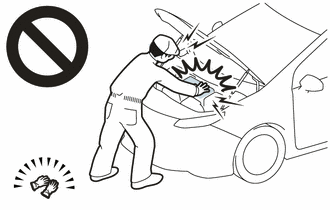
Before the following operations are conducted, take precautions to prevent electric shock by turning the ignition switch off, wearing insulated gloves, and removing the service plug grip from HV battery.
- Inspecting the high-voltage system
- Disconnecting the low voltage connector of the inverter with converter assembly
- Disconnecting the low voltage connector of the HV battery
-
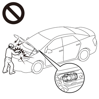
To prevent electric shock, make sure to remove the service plug grip to cut off the high voltage circuit before servicing the vehicle.
-
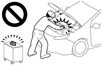
After removing the service plug grip from the HV battery, put it in your pocket to prevent other technicians from accidentally reconnecting it while you are working on the high-voltage system.
-
After removing the service plug grip, wait for at least 10 minutes before touching any of the high-voltage connectors or terminals. After waiting for 10 minutes, check the voltage at the terminals in the inspection point in the inverter with converter assembly. The voltage should be 0 V before beginning work.
Click here
HINT:
Waiting for at least 10 minutes is required to discharge the high-voltage capacitor inside the inverter with converter assembly.
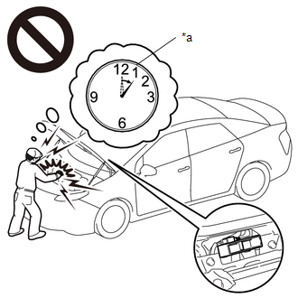
*a
Without waiting for 10 minutes
NOTICE:
After turning the ignition switch off, waiting time may be required before disconnecting the cable from the negative (-) auxiliary battery terminal. Therefore, make sure to read the disconnecting the cable from the negative (-) auxiliary battery terminal notices before proceeding with work.
Click here
PROCEDURE
|
1. |
CLEAR DTC |
(a) Connect the Techstream to the DLC3.
(b) Turn the ignition switch to ON.
(c) Turn the Techstream on.
(d) Enter the following menus: Powertrain / Motor Generator / Trouble Codes.
(e) Clear the DTCs.
Powertrain > Motor Generator > Clear DTCs
(f) Turn the ignition switch off.
|

|
2. |
CHECK DIAGNOSIS RELATED INFORMATION AND DTC OUTPUT (MOTOR GENERATOR) |
(a) Connect the Techstream to the DLC3.
(b) Turn the ignition switch to ON and wait for 2 minutes or more.
(c) Enter the following menus: Powertrain / Motor Generator / Utility / Diagnosis Related Information.
Powertrain > Motor Generator > Utility
|
Tester Display |
|---|
|
Diagnosis Related Information |
(d) Enter the following menus: Powertrain / Motor Generator / Trouble Codes.
Powertrain > Motor Generator > Trouble Codes
(e) Check for DTCs.
|
Result |
Proceed to |
|---|---|
|
P31241F or P312487 is listed in Diagnosis Related Information or P31241F or P312487 is output. |
A |
|
P31241F and P312487 are not listed in Diagnosis Information and P31241F and P312487 are not output. |
B |
(f) Turn the ignition switch off.
| B |

|
|
|
3. |
CHECK HYBRID VEHICLE CONTROL ECU ASSEMBLY (CHECK WAVEFORM) |
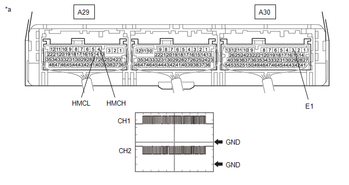
(a) Connect an oscilloscope between the hybrid vehicle control ECU assembly terminals specified in the following table.
(b) Turn the ignition switch to ON.
(c) Measure the waveform.
|
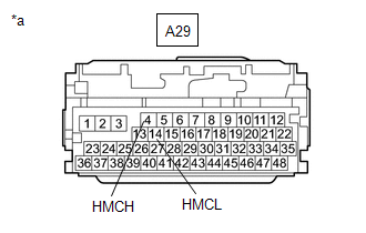
*a |
Component with harness connected (Hybrid Vehicle Control ECU Assembly) |
- |
- |
|
Item |
Contents |
|---|---|
|
Tester Connection |
CH1: A29-4 (HMCH) - A30-3 (E1) CH2: A29-14 (HMCL) - A30-3 (E1) |
|
Equipment Setting |
1 V/DIV., 200 μs./DIV. |
|
Condition |
Ignition switch ON |
|
Result |
Proceed to |
|---|---|
|
The waveform appears as shown in the illustration. |
A |
|
The waveform differs from the one shown in the illustration. |
B |
HINT:
- Perform this inspection with the connector connected.
- If pulses are generated, the shape of the waveform can be assumed to be normal.
- The shape of the waveform may vary according to communication conditions.
(d) Turn the ignition switch off.
| A |
|
|
|
4. |
CHECK CONNECTOR CONNECTION CONDITION (HYBRID VEHICLE CONTROL ECU ASSEMBLY CONNECTOR) |
|
(a) Check the connector connections and contact pressure of the relevant terminals for the hybrid vehicle control ECU assembly connectors. Click here
OK: The connectors are connected securely and there are no contact pressure problems. |
|
| NG |
|
CONNECT SECURELY |
|
|
5. |
CHECK CONNECTOR CONNECTION CONDITION (INVERTER WITH CONVERTER ASSEMBLY CONNECTOR) |
CAUTION:
Be sure to wear insulated gloves.
(a) Check that the service plug grip is not installed.
NOTICE:
After removing the service plug grip, do not turn the ignition switch to ON (READY), unless instructed by the repair manual because this may cause a malfunction.
|
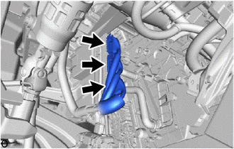
(b) Check the connection condition of the low voltage connectors of the inverter with converter assembly and the contact pressure of each terminal. Check the terminals for deformation, and the connector for water and foreign matter. Click here
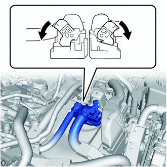
NOTICE: Before disconnecting the connector, confirm that it is properly connected by checking that the claws of the lock levers are engaged and that the connector cannot be pulled off. OK: - The connector is connected securely. - The terminals are not deformed and are connected securely. - No water or foreign matter in the connector. Result:
HINT: When connecting the connector, connect it with the lock levers raised. Rotate each lock lever downward and make sure that the connector is securely connected. When a lock lever is fully lowered, a click will be heard as its claw engages. After the click is heard, pull up on the connector to confirm that it is securely connected. |
|
| B |
|
CONNECT SECURELY |
| C |
|
REPAIR OR REPLACE HARNESS OR CONNECTOR |
|
|
6. |
CHECK HARNESS AND CONNECTOR (HYBRID VEHICLE CONTROL ECU ASSEMBLY - INVERTER WITH CONVERTER ASSEMBLY) |
CAUTION:
Be sure to wear insulated gloves.
(a) Check that the service plug grip is not installed.
NOTICE:
After removing the service plug grip, do not turn the ignition switch to ON (READY), unless instructed by the repair manual because this may cause a malfunction.
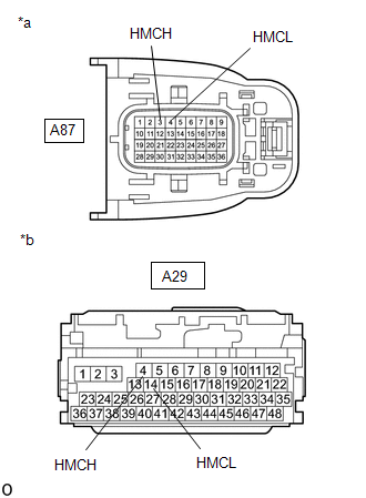
(b) Disconnect the A87 inverter with converter assembly connector.
(c) Disconnect the A29 hybrid vehicle control ECU assembly connector.
|
(d) Measure the resistance according to the value(s) in the table below. Standard Resistance (Check for Open):
Standard Resistance (Check for Short):
HINT: As there might be an intermittent malfunction, inspect the following items even if the measured resistance is as specified. Check that each connector between the inverter with converter assembly and hybrid vehicle control ECU assembly is not loose or disconnected. |
|
(e) Connect the cable to the negative (-) auxiliary battery terminal.
(f) Turn the ignition switch to ON.
(g) Measure the voltage according to the value(s) in the table below.
Standard Voltage:
|
Tester Connection |
Condition |
Specified Condition |
|---|---|---|
|
A87-3 (HMCH) or A29-4 (HMCH) - Body ground and other terminals |
Ignition switch ON |
Below 1 V |
|
A87-4 (HMCL) or A29-14 (HMCL) - Body ground and other terminals |
Ignition switch ON |
Below 1 V |
NOTICE:
Turning the ignition switch to ON with the hybrid vehicle control ECU assembly and inverter with converter assembly connectors disconnected causes other DTCs to be stored. Clear the DTCs after performing this inspection.
(h) Turn the ignition switch off.
(i) Reconnect the A29 hybrid vehicle control ECU assembly connector.
(j) Reconnect the A87 inverter with converter assembly connector.
| NG |
|
REPAIR OR REPLACE HARNESS OR CONNECTOR |
|
|
7. |
CHECK INVERTER WITH CONVERTER ASSEMBLY |
(a) Disconnect the A29 hybrid vehicle control ECU assembly connector.
|
(b) Measure the resistance according to the value(s) in the table below. Standard Resistance:
|
|
(c) Reconnect the A29 hybrid vehicle control ECU assembly connector.
| OK |
|
REPLACE HYBRID VEHICLE CONTROL ECU ASSEMBLY
|
| NG |
|
|
|
|