- Crank Position (Hybrid control system)
- Engine Speed (Hybrid control system)
| Last Modified: 01-30-2024 | 6.11:8.1.0 | Doc ID: RM100000001OQZD |
| Model Year Start: 2020 | Model: RAV4 HV | Prod Date Range: [06/2020 - ] |
| Title: HYBRID / BATTERY CONTROL: MOTOR GENERATOR CONTROL SYSTEM (for LITHIUM-ION BATTERY): P034000,P034031; Camshaft Position Sensor "A" Circuit Bank 1 or Single Sensor; 2020 - 2024 MY RAV4 HV [06/2020 - ] | ||
|
DTC |
P034000 |
Camshaft Position Sensor "A" Circuit Bank 1 or Single Sensor |
|
DTC |
P034031 |
Camshaft Position Sensor "A" Circuit Bank 1 or Single Sensor No Signal |
DESCRIPTION
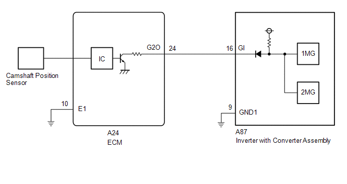
If the cam position signal pulse sent from the ECM via a direct line is abnormal, the motor generator control ECU (MG ECU) (built into the inverter with converter assembly) stores DTC P034000 or P034031.
|
DTC No. |
Detection Item |
DTC Detection Condition |
Trouble Area |
MIL |
Warning Indicate |
|---|---|---|---|---|---|
|
P034000 |
Camshaft Position Sensor "A" Circuit Bank 1 or Single Sensor |
GI signal (camshaft position sensor) is not input for 2 sec. or more while the engine is running* (1 trip detection logic) |
|
Does not come on |
Master Warning: Comes on |
|
P034031 |
Camshaft Position Sensor "A" Circuit Bank 1 or Single Sensor No Signal |
GI signal (camshaft position sensor) is not input for 2 sec. or more while the engine is running* (1 trip detection logic) |
|
Does not come on |
Master Warning: Comes on |
HINT:
*: When this DTC is stored, vibration may occur when the engine is stopped.
Related Data List
|
DTC No. |
Data List |
|---|---|
|
P034000 P034031 |
|
CONFIRMATION DRIVING PATTERN
HINT:
After repair has been completed, clear the DTC and then check that the vehicle has returned to normal by performing the following All Readiness check procedure.
Click here
![2020 - 2024 MY RAV4 HV [06/2020 - ]; HYBRID / BATTERY CONTROL: MOTOR GENERATOR CONTROL SYSTEM (for LITHIUM-ION BATTERY): UTILITY](/t3Portal/stylegraphics/info.gif)
- Connect the Techstream to the DLC3.
- Turn the ignition switch to ON and turn the Techstream on.
- Clear the DTCs (even if no DTCs are stored, perform the clear DTC procedure).
- Turn the ignition switch off and wait for 2 minutes or more.
- Turn the ignition switch to ON and turn the Techstream on.
- Turn the ignition switch to ON (READY).
- With the vehicle stopped, move the shift lever to P.
- Depress the accelerator pedal to start the engine.
-
Depress the accelerator pedal and maintain the engine speed at 1000 rpm or more for 5 seconds or more.
NOTICE:
As the state of charge of the HV battery may be low after driving in fail-safe mode, it will automatically be charged for 5 to 10 minutes with ignition switch ON (READY) after repairs have been performed.
- Enter the following menus: Powertrain / Motor Generator / Utility / All Readiness.
-
Check the DTC judgment result.
HINT:
- If the judgment result shows NORMAL, the system is normal.
- If the judgment result shows ABNORMAL, the system has a malfunction.
- If the judgment result shows INCOMPLETE, perform driving pattern again.
WIRING DIAGRAM
CAUTION / NOTICE / HINT
CAUTION:
-
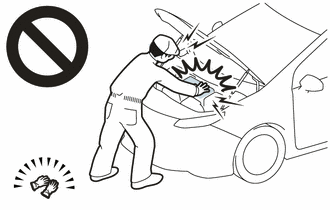
Before the following operations are conducted, take precautions to prevent electric shock by turning the ignition switch off, wearing insulated gloves, and removing the service plug grip from HV battery.
- Inspecting the high-voltage system
- Disconnecting the low voltage connector of the inverter with converter assembly
- Disconnecting the low voltage connector of the HV battery
-
To prevent electric shock, make sure to remove the service plug grip to cut off the high voltage circuit before servicing the vehicle.
-
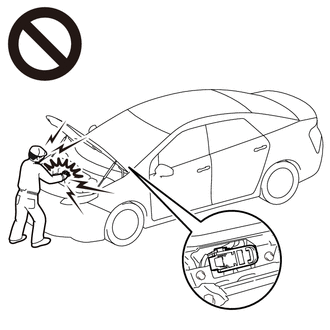
After removing the service plug grip from the HV battery, put it in your pocket to prevent other technicians from accidentally reconnecting it while you are working on the high-voltage system.
-
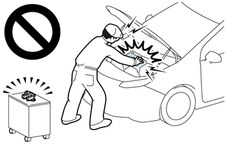
After removing the service plug grip, wait for at least 10 minutes before touching any of the high-voltage connectors or terminals. After waiting for 10 minutes, check the voltage at the terminals in the inspection point in the inverter with converter assembly. The voltage should be 0 V before beginning work.
Click here
HINT:
Waiting for at least 10 minutes is required to discharge the high-voltage capacitor inside the inverter with converter assembly.
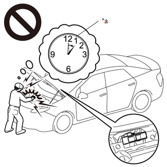
*a
Without waiting for 10 minutes
NOTICE:
After turning the ignition switch off, waiting time may be required before disconnecting the cable from the negative (-) auxiliary battery terminal. Therefore, make sure to read the disconnecting the cable from the negative (-) auxiliary battery terminal notices before proceeding with work.
Click here
PROCEDURE
|
1. |
CHECK DTC OUTPUT (ENGINE) |
(a) Connect the Techstream to the DLC3.
(b) Turn the ignition switch to ON.
(c) Enter the following menus: Powertrain / Engine / Trouble Codes.
(d) Check for DTCs.
Powertrain > Engine > Trouble Codes
|
Result |
Proceed to |
|---|---|
|
SFI system DTCs are not output. |
A |
|
Any of the following DTCs are also output. |
B |
|
Relevant DTC |
|
|---|---|
|
P034011 |
Camshaft Position Sensor "A" Bank 1 or Single Sensor Circuit Short to Ground |
|
P034015 |
Camshaft Position Sensor "A" Bank 1 or Single Sensor Circuit Short to Battery or Open |
|
P034031 |
Camshaft Position Sensor "A" Bank 1 or Single Sensor No Signal |
(e) Turn the ignition switch off.
| B |

|
GO TO DTC CHART (SFI SYSTEM)
|
|

|
2. |
CHECK DTC OUTPUT (MOTOR GENERATOR) |
(a) Connect the Techstream to the DLC3.
(b) Turn the ignition switch to ON.
(c) Enter the following menus: Powertrain / Motor Generator / Trouble Codes.
(d) Check for DTCs.
Powertrain > Motor Generator > Trouble Codes
|
Result |
Proceed to |
|---|---|
|
None of the following DTCs are output. |
A |
|
Any of the following DTCs are also output. |
B |
|
Relevant DTC |
|
|---|---|
|
P06B01C |
Generator Control Module Position Sensor REF Power Source Circuit Voltage Out of Range |
|
P06D61C |
Generator Control Module Offset Power Circuit Voltage Out of Range |
|
P0A1B1F |
Generator Control Module Circuit Intermittent |
|
P1C2B49 |
Drive Motor "A" Control Module A/D Converter Circuit Internal Electronic Failure |
|
P1C2B1C |
Drive Motor "A" Control Module A/D Converter Circuit Voltage Out of Range |
|
P1CAD49 |
Drive Motor "A" Position Sensor Internal Electronic Failure |
|
P1CB038 |
Drive Motor "A" Position Sensor REF Signal Frequency Incorrect |
|
P313487 |
Communication Error from Drive Motor "A" to Generator Missing Message |
|
P313483 |
Communication Error from Drive Motor "A" to Generator Value of Signal Protection Calculation Incorrect |
|
P313486 |
Communication Error from Drive Motor "A" to Generator Signal Invalid |
HINT:
P034000 or P034031 may be stored due to a malfunction which also causes the DTCs in the preceding table to be stored. In this case, first troubleshoot the output DTCs in the preceding table. Then, perform a test to attempt to reproduce the problems, and check that no DTCs are output.
(e) Turn the ignition switch off.
| B |
|
|
|
3. |
CHECK CONNECTOR CONNECTION CONDITION (INVERTER WITH CONVERTER ASSEMBLY CONNECTOR) |
Click here
|
Result |
Proceed to |
|---|---|
|
OK |
A |
|
NG (The connector is not connected securely.) |
B |
|
NG (The terminals are not making secure contact or are deformed, or water or foreign matter exists in the connector.) |
C |
| B |
|
CONNECT SECURELY |
| C |
|
REPAIR OR REPLACE HARNESS OR CONNECTOR |
|
|
4. |
CHECK CONNECTOR CONNECTION CONDITION (ECM CONNECTOR) |
Click here
| NG |
|
CONNECT SECURELY |
|
|
5. |
CHECK HARNESS AND CONNECTOR (INVERTER WITH CONVERTER ASSEMBLY - ECM) |
CAUTION:
Be sure to wear insulated gloves.
(a) Check that the service plug grip is not installed.
NOTICE:
After removing the service plug grip, do not turn the ignition switch to ON (READY), unless instructed by the repair manual because this may cause a malfunction.
(b) Disconnect the A87 inverter with converter assembly connector.
(c) Disconnect the A24 ECM connector.
(d) Connect the cable to the negative (-) auxiliary battery terminal.
(e) Turn the ignition switch to ON.
|
(f) Measure the voltage according to the value(s) in the table below. Standard Voltage:
NOTICE: Turning the ignition switch to ON with the inverter with converter assembly connector and ECM connector disconnected causes other DTCs to be stored. Clear the DTCs after performing this inspection. |
|
(g) Turn the ignition switch off.
(h) Measure the resistance according to the value(s) in the table below.
Standard Resistance (Check for Open):
|
Tester Connection |
Condition |
Specified Condition |
|---|---|---|
|
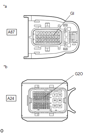
A87-16 (GI) - A24-24 (G2O) |
Ignition switch off |
Below 1 Ω |
Standard Resistance (Check for Short):
|
Tester Connection |
Condition |
Specified Condition |
|---|---|---|
|
A87-16 (GI) or A24-24 (G2O) - Body ground and other terminals |
Ignition switch off |
10 kΩ or higher |
(i) Disconnect the cable from the negative (-) auxiliary battery terminal.
(j) Reconnect the A24 ECM connector.
(k) Reconnect the A87 inverter with converter assembly connector.
| NG |
|
REPAIR OR REPLACE HARNESS OR CONNECTOR |
|
|
6. |
CHECK ECM |
(a) Disconnect the A24 ECM connector.
(b) Measure the resistance according to the value(s) in the table below.
|
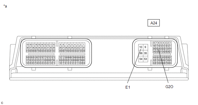
*a |
Component without harness connected (ECM) |
- |
- |
Standard Resistance:
|
Tester Connection |
Condition |
Specified Condition |
|---|---|---|
|
A24-24 (G2O) - A24-10 (E1) |
Ignition switch off |
10 kΩ or higher |
(c) Reconnect the A24 ECM connector.
| OK |
|
| NG |
|
REPLACE ECM
|
|
|
|