| Last Modified: 01-30-2024 | 6.11:8.1.0 | Doc ID: RM100000001OBBX |
| Model Year Start: 2020 | Model: RAV4 HV | Prod Date Range: [06/2020 - ] |
| Title: HYBRID / BATTERY CONTROL: HYBRID CONTROL SYSTEM (for LITHIUM-ION BATTERY): Rear Motor High-voltage Circuit; 2020 - 2024 MY RAV4 HV [06/2020 - ] | ||
|
Rear Motor High-voltage Circuit |
DESCRIPTION
The cause of the malfunction may be the high-voltage circuit of the rear motor.
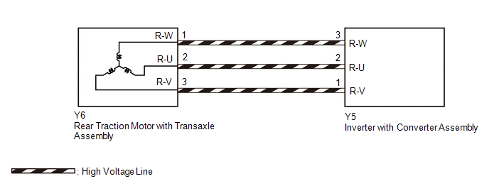
Check the rear motor internal resistance and the connection condition of the high-voltage line between the inverter and rear motor to check whether there is an open or short circuit.
Related Parts Check
|
Area |
Inspection |
|---|---|
|
HV floor under wire (rear traction motor cable) connection check |
Check for open or short circuit in the connection condition of the cable from the inverter to the rear motor. |
|
Rear motor or HV floor under wire (rear traction motor cable) |
Check the rear motor (including cable) internal resistance and the insulation resistance with body ground to check for an open or short circuit. |
WIRING DIAGRAM
CAUTION / NOTICE / HINT
This diagnostic procedure is referenced to in the diagnostic procedure of several DTCs.
If the result of this diagnostic procedure is normal, proceed as directed in the procedure for the DTC.
CAUTION:
-
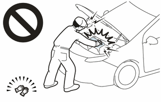
Before the following operations are conducted, take precautions to prevent electric shock by turning the ignition switch off, wearing insulated gloves, and removing the service plug grip from HV battery.
- Inspecting the high-voltage system
- Disconnecting the low voltage connector of the inverter with converter assembly
- Disconnecting the low voltage connector of the HV battery
-
To prevent electric shock, make sure to remove the service plug grip to cut off the high voltage circuit before servicing the vehicle.
-
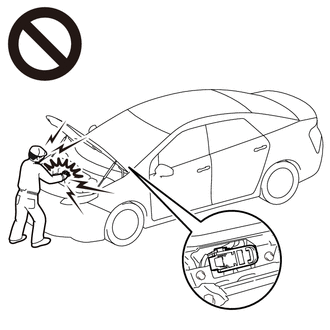
After removing the service plug grip from the HV battery, put it in your pocket to prevent other technicians from accidentally reconnecting it while you are working on the high-voltage system.
-
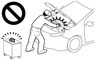
After removing the service plug grip, wait for at least 10 minutes before touching any of the high-voltage connectors or terminals. After waiting for 10 minutes, check the voltage at the terminals in the inspection point in the inverter with converter assembly. The voltage should be 0 V before beginning work.
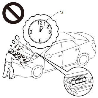
*a
Without waiting for 10 minutes
Click here
![2020 - 2024 MY RAV4 HV [06/2020 - ]; HYBRID / BATTERY CONTROL: HYBRID CONTROL SYSTEM (for LITHIUM-ION BATTERY): PRECAUTION](/t3Portal/stylegraphics/info.gif)
HINT:
Waiting for at least 10 minutes is required to discharge the high-voltage capacitor inside the inverter with converter assembly.
NOTICE:
After turning the ignition switch off, waiting time may be required before disconnecting the cable from the negative (-) auxiliary battery terminal. Therefore, make sure to read the disconnecting the cable from the negative (-) auxiliary battery terminal notices before proceeding with work.
Click here
PROCEDURE
|
1. |
CHECK INVERTER WITH CONVERTER ASSEMBLY (HV FLOOR UNDER WIRE (REAR TRACTION MOTOR CABLE) CONNECTION CONDITION) |
CAUTION:
Be sure to wear insulated gloves.
(a) Check that the service plug grip is not installed.
NOTICE:
After removing the service plug grip, do not turn the ignition switch to ON (READY), unless instructed by the repair manual because this may cause a malfunction.
|
(b) Check that the bolts for the HV floor under wire (rear traction motor cable) are tightened to the specified torque, the HV floor under wire (rear traction motor cable) is connected securely, and there are no contact problems. Specified Condition: T = 8.0 N*m (82 kgf*cm, 71 in.*lbf) |
|
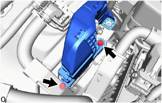
(c) Disconnect the HV floor under wire (rear traction motor cable) from the inverter with converter assembly.
(d) Check for arc marks at the terminals for the HV floor under wire (rear traction motor cable).
|
Result |
Proceed to |
|
|---|---|---|
|
The terminals are connected securely and there are no contact problems. |
There are no arc marks. |
A |
|
The terminals are not connected securely and there is a contact problem. |
There are arc marks. |
B |
|
The terminals are not connected securely and there is a contact problem. |
There are no arc marks. |
C |
|
The terminals are connected securely and there are no contact problems. |
There are arc marks. |
B |
(e) Reconnect the HV floor under wire (rear traction motor cable).
| B |

|
REPLACE MALFUNCTIONING PARTS |
| C |
|
CONNECT SECURELY |
|

|
2. |
CHECK REAR TRACTION MOTOR WITH TRANSAXLE ASSEMBLY (REAR MOTOR (MGR)) |
CAUTION:
Be sure to wear insulated gloves.
(a) Check that the service plug grip is not installed.
NOTICE:
After removing the service plug grip, do not turn the ignition switch to ON (READY), unless instructed by the repair manual because this may cause a malfunction.
|
(b) Disconnect the HV floor under wire (rear traction motor cable) from the inverter with converter assembly. |
|
|
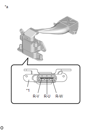
(c) Using a milliohmmeter, measure the resistance according to the value(s) in the table below. HINT: If the rear motor (MGR) temperature is high, the resistance will vary greatly from the specification. Therefore, measure the resistance at least 8 hours after the vehicle is stopped. Standard Resistance:
HINT: To correct the variation of the measured resistance due to temperature, use the following formula to calculate the resistance at 20°C (68°F). R20 = Rt / {1 + 0.00393 X (T - 20)} The calculation is based on the following: R20: Resistance at 20°C (68°F) (mΩ) Rt: Measured resistance (mΩ) T: Temperature when the resistance is measured (°C (°F).) |
|
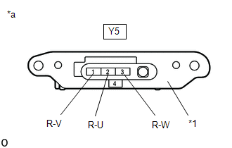
(d) Using a megohmmeter set to 500 V, measure the resistance according to the value(s) in the table below.
NOTICE:
Be sure to set the megohmmeter to 500 V when performing this test. Using a setting higher than 500 V can result in damage to the component being inspected.
Standard Resistance:
|
Tester Connection |
Condition |
Specified Condition |
|---|---|---|
|
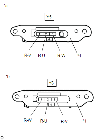
Y5-1 (R-V) - Body ground and shield ground |
Ignition switch off |
10 MΩ or higher |
|
Y5-2 (R-U) - Body ground and shield ground |
Ignition switch off |
10 MΩ or higher |
|
Y5-3 (R-W) - Body ground and shield ground |
Ignition switch off |
10 MΩ or higher |
(e) Reconnect the HV floor under wire (rear traction motor cable).
| OK |
|
REAR MOTOR HIGH-VOLTAGE CIRCUIT NORMAL (PERFORM NEXT STEP FOR REFERENCED DTC) |
|
|
3. |
CHECK REAR TRACTION MOTOR WITH TRANSAXLE ASSEMBLY (HV FLOOR UNDER WIRE (REAR TRACTION MOTOR CABLE) CONNECTION CONDITION) |
CAUTION:
Be sure to wear insulated gloves.
(a) Check that the service plug grip is not installed.
NOTICE:
After removing the service plug grip, do not turn the ignition switch to ON (READY), unless instructed by the repair manual because this may cause a malfunction.
|
(b) Check that the bolts for the HV floor under wire (rear traction motor cable) are tightened to the specified torque, the HV floor under wire (rear traction motor cable) is connected securely, and there are no contact problems. Specified Condition: T=8.0 N*m (82 kgf*cm, 71 in.*lbf) |
|
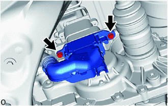
(c) Disconnect the HV floor under wire (rear traction motor cable) from the rear traction motor with transaxle assembly.
(d) Check for arc marks at the terminals for the HV floor under wire (rear traction motor cable).
|
Result |
Proceed to |
|
|---|---|---|
|
The terminals are connected securely and there are no contact problems. |
There are no arc marks. |
A |
|
The terminals are not connected securely and there is a contact problem. |
There are arc marks. |
B |
|
The terminals are not connected securely and there is a contact problem. |
There are no arc marks. |
C |
|
The terminals are connected securely and there are no contact problems. |
There are arc marks. |
B |
(e) Reconnect the HV floor under wire (rear traction motor cable).
| B |
|
REPLACE MALFUNCTIONING PARTS |
| C |
|
CONNECT SECURELY |
|
|
4. |
CHECK FLOOR UNDER WIRE (REAR TRACTION MOTOR CABLE) |
CAUTION:
Be sure to wear insulated gloves.
(a) Check that the service plug grip is not installed.
NOTICE:
After removing the service plug grip, do not turn the ignition switch to ON (READY), unless instructed by the repair manual because this may cause a malfunction.
|
(b) Disconnect the HV floor under wire (rear traction motor cable) from the inverter with converter assembly. |
|
|
(c) Disconnect the HV floor under wire (rear traction motor cable) from the rear traction motor with transaxle assembly. |
|
|
(d) Using a megohmmeter set to 500 V, measure the resistance according to the value(s) in the table below. NOTICE: Be sure to set the megohmmeter to 500 V when performing this test. Using a setting higher than 500 V can result in damage to the component being inspected. Standard Resistance:
NOTICE: Wrap the terminals of the motor cable with insulating tape to prevent them from coming into contact with body ground. |
|
(e) Measure the resistance according to the value(s) in the table below.
Standard Resistance:
|
Tester Connection |
Condition |
Specified Condition |
|---|---|---|
|
Y5-3 (R-W) - Y6-1 (R-W) |
Ignition switch off |
Below 1 Ω |
|
Y5-1 (R-V) - Y6-3 (R-V) |
Ignition switch off |
Below 1 Ω |
|
Y5-2 (R-U) - Y6-2 (R-U) |
Ignition switch off |
Below 1 Ω |
|
Y5-3 (R-W) - Y6-2 (R-U) |
Ignition switch off |
10 MΩ or higher |
|
Y5-1 (R-V) - Y6-1 (R-W) |
Ignition switch off |
10 MΩ or higher |
|
Y5-2 (R-U) - Y6-3 (R-V) |
Ignition switch off |
10 MΩ or higher |
(f) Reconnect the HV floor under wire (rear traction motor cable) to the rear traction motor with transaxle assembly.
(g) Reconnect the HV floor under wire (rear traction motor cable) to the inverter with converter assembly.
| NG |
|
REPLACE FLOOR UNDER WIRE
|
|
|
5. |
CHECK REAR TRACTION MOTOR CABLE |
CAUTION:
Be sure to wear insulated gloves.
(a) Check that the service plug grip is not installed.
NOTICE:
After removing the service plug grip, do not turn the power switch on (READY), unless instructed by the repair manual because this may cause a malfunction.
(b) Remove the rear traction motor cable from the rear traction motor with transaxle assembly.
Click here
|
(c) Using a megohmmeter set to 500 V, measure the resistance according to the value(s) in the table below. NOTICE: Be sure to set the megohmmeter to 500 V when performing this test. Using a setting higher than 500 V can result in damage to the component being inspected. Standard Resistance:
|
|
(d) Install the rear traction motor cable.
| OK |
|
REPLACE REAR TRACTION MOTOR WITH TRANSAXLE ASSEMBLY
|
| NG |
|
REPLACE REAR TRACTION MOTOR CABLE
|
|
|
|