| Last Modified: 01-30-2024 | 6.11:8.1.0 | Doc ID: RM100000001O4J9 |
| Model Year Start: 2020 | Model: RAV4 | Prod Date Range: [06/2020 - 08/2020] |
| Title: BRAKE CONTROL / DYNAMIC CONTROL SYSTEMS: ELECTRONICALLY CONTROLLED BRAKE SYSTEM (w/o Vacuum Brake Booster): C1241,C1242; Low or High Power Supply Voltage; 2020 MY RAV4 RAV4 HV [06/2020 - 08/2020] | ||
|
DTC |
C1241 |
Low or High Power Supply Voltage |
|
DTC |
C1242 |
Open Circuit in IG1/IG2 Power Source Circuit |
DESCRIPTION
If a malfunction is detected in the power supply circuit, the skid control ECU (brake booster with master cylinder assembly) power source voltage drops, or there is insufficient voltage to operate the ABS main relay, the skid control ECU (brake booster with master cylinder assembly) will store these DTCs.
These DTCs may also be stored if the auxiliary battery voltage drops below 9.5 V.
HINT:
DTC C1256 (Accumulator Low Pressure) may also be memorized if there is a drop in power source voltage.
|
DTC No. |
Detection Item |
INF Code |
DTC Detection Condition |
Trouble Area |
Note |
|---|---|---|---|---|---|
|
C1241 |
Low or High Power Supply Voltage |
101 102 551 552 553 |
|
|
- |
|
C1242 |
Open Circuit in IG1/IG2 Power Source Circuit |
111 112 |
|
|
- |
DTC Detection Conditions: C1241 INF Code: 101
|
Vehicle Condition |
||||
|---|---|---|---|---|
|
Pattern 1 |
Pattern 2 |
Pattern 3 |
||
|
Diagnosis Condition |
BS terminal voltage is 9.3 V or less |
○ |
○ |
○ |
|
Malfunction Status |
Vehicle not decelerated (brake pedal is not depressed) |
○ |
- |
- |
|
While depressing the brake pedal, linear solenoid current does not satisfy 1.34 A |
- |
○ |
- |
|
|
Vehicle decelerated (brake pedal is depressed) |
- |
- |
○ |
|
|
Detection Time |
3 seconds or more |
- |
0.06 seconds |
|
|
Number of Trips |
1 trip |
1 trip |
1 trip |
|
HINT:
DTC will be output when conditions for either of the patterns in the table above are met.
DTC Detection Conditions: C1241 INF Code: 102
|
Vehicle Condition |
|||||
|---|---|---|---|---|---|
|
Pattern 1 |
Pattern 2 |
Pattern 3 |
Pattern 4 |
||
|
Diagnosis Condition |
ECU internal voltage is 6.8 V or less |
○ |
○ |
○ |
○ |
|
Malfunction Status |
With the ignition switch off, the main relay contact voltage does not reach 3.5 V or more continuously for 0.22 seconds or more in response to a main relay ON command |
○ |
- |
- |
- |
|
With the ignition switch off and the IG1 terminal voltage 9.5 V or less, the main relay contact voltage does not reach 3.5 V or more continuously for 0.22 seconds or more in response to a main relay ON command |
- |
○ |
- |
- |
|
|
Sensor supply voltage is 4.75 V or less, or 5.25 V or more |
- |
- |
○ |
- |
|
|
Accumulator pressure sensor output voltage is 4.54 V or less, or 5.46 V or more |
- |
- |
- |
○ |
|
|
Detection Time |
- |
- |
0.06 seconds |
0.06 seconds |
|
|
Number of Trips |
1 trip |
1 trip |
1 trip |
1 trip |
|
HINT:
DTC will be output when conditions for either of the patterns in the table above are met.
DTC Detection Conditions: C1242 INF Code: 112
|
Vehicle Condition |
|||
|---|---|---|---|
|
Pattern 1 |
Pattern 2 |
||
|
Diagnosis Condition |
- |
- |
- |
|
Malfunction Status |
While hybrid vehicle control ECU assembly communication is enabled, no voltage (below 3.5 V) is applied to the IG2 terminal and the power source voltage (exceeding 9.5 V) is applied to the IG1 terminal continuously |
○ |
- |
|
When the vehicle speed exceeds 10 km/h, no voltage (below 3.5 V) is applied to the IG2 terminal and the power source voltage (exceeding 9.5 V) is applied to the IG1 terminal continuously |
- |
○ |
|
|
Detection Time |
4 seconds or more |
4 seconds or more |
|
|
Number of Trips |
1 trip |
1 trip |
|
HINT:
DTC will be output when conditions for either of the patterns in the table above are met.
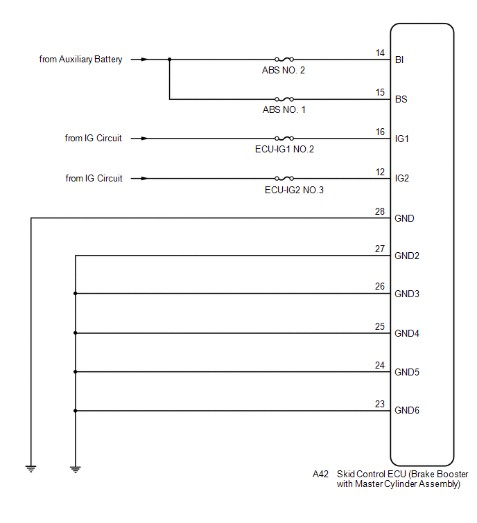
WIRING DIAGRAM

CAUTION / NOTICE / HINT
NOTICE:
PROCEDURE
|
1. |
CHECK SMART KEY SYSTEM (for Start Function) |
(a) Check if smart key system (for start function) DTCs are output.
Body Electrical > Smart Access > Trouble Codes
|
Result |
Proceed to |
|---|---|
|
DTCs are not output. |
A |
|
DTCs are output. |
B |
| B |

|
|
|
2. |
CHECK HYBRID CONTROL SYSTEM |
(a) Check if hybrid control system DTCs are output.
for 2WD with NICKEL METAL HYDRIDE BATTERY: Click here
![2019 - 2020 MY RAV4 HV [11/2018 - 08/2020]; HYBRID / BATTERY CONTROL: HYBRID CONTROL SYSTEM (for 2WD with NICKEL METAL HYDRIDE BATTERY): DTC CHECK / CLEAR](/t3Portal/stylegraphics/info.gif)
for AWD with NICKEL METAL HYDRIDE BATTERY: Click here
![2019 - 2022 MY RAV4 HV [02/2019 - 10/2022]; HYBRID / BATTERY CONTROL: HYBRID CONTROL SYSTEM (for AWD with NICKEL METAL HYDRIDE BATTERY): DTC CHECK / CLEAR](/t3Portal/stylegraphics/info.gif)
for LITHIUM-ION BATTERY: Click here
![2020 - 2022 MY RAV4 HV [06/2020 - 10/2022]; HYBRID / BATTERY CONTROL: HYBRID CONTROL SYSTEM (for LITHIUM-ION BATTERY): DTC CHECK / CLEAR](/t3Portal/stylegraphics/info.gif)
Powertrain > Hybrid Control > Trouble Codes
|
Result |
Proceed to |
|---|---|
|
DTCs are not output. |
A |
|
DTCs are output. |
B |
| B |

|
INSPECT HYBRID CONTROL SYSTEM for 2WD with NICKEL METAL HYDRIDE BATTERY: Click here
|
|
|
3. |
CHECK DTC |
(a) Check that no main relay malfunction DTCs are output.
Chassis > ABS/VSC/TRAC > Trouble Codes
|
Result |
Proceed to |
|---|---|
|
Main relay malfunction DTCs are not output. |
A |
|
Main relay malfunction DTCs are output. |
B |
| B |

|
|
|
4. |
CHECK AUXILIARY BATTERY |
(a) Check the auxiliary battery voltage.
Standard Voltage:
|
Tester Connection |
Switch Condition |
Specified Condition |
|---|---|---|
|
Auxiliary battery |
Ignition switch ON |
11 to 14 V |
|
Auxiliary battery |
Ignition switch ON (READY) |
11 to 15.5 V |
| NG |

|
CHARGE OR REPLACE AUXILIARY BATTERY |
|
|
5. |
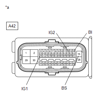
CHECK HARNESS AND CONNECTOR (POWER SOURCE TERMINAL) |
|
(a) Make sure that there is no looseness at the locking part and the connecting part of the connector. |
|
(b) Disconnect the A42 skid control ECU (brake booster with master cylinder assembly) connector.
(c) Measure the voltage according to the value(s) in the table below.
Standard Voltage:
|
Tester Connection |
Condition |
Specified Condition |
|---|---|---|
|
A42-14 (BI) - Body ground |
Always |
11 to 14 V |
|
A42-15 (BS) - Body ground |
Always |
11 to 14 V |
|
A42-16 (IG1) - Body ground |
Ignition switch ON |
11 to 14 V |
|
A42-12 (IG2) - Body ground |
Ignition switch ON |
11 to 14 V |
| NG |

|
REPAIR OR REPLACE HARNESS OR CONNECTOR (POWER SOURCE CIRCUIT) |
|
|
6. |
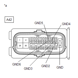
CHECK HARNESS AND CONNECTOR (GND TERMINAL) |
|
(a) Turn the ignition switch off. |
|
(b) Measure the resistance according to the value(s) in the table below.
Standard Resistance:
|
Tester Connection |
Condition |
Specified Condition |
|---|---|---|
|
A42-28 (GND) - Body ground |
Always |
Below 1 Ω |
|
A42-27 (GND2) - Body ground |
Always |
Below 1 Ω |
|
A42-26 (GND3) - Body ground |
Always |
Below 1 Ω |
|
A42-25 (GND4) - Body ground |
Always |
Below 1 Ω |
|
A42-24 (GND5) - Body ground |
Always |
Below 1 Ω |
|
A42-23 (GND6) - Body ground |
Always |
Below 1 Ω |
| NG |

|
REPAIR OR REPLACE HARNESS OR CONNECTOR (GND CIRCUIT) |
|
|
7. |
RECONFIRM DTC |
(a) Reconnect the A42 skid control ECU (brake booster with master cylinder assembly) connector.
(b) Clear the DTCs.
Chassis > ABS/VSC/TRAC > Clear DTCs
(c) Turn the ignition switch off.
(d) Turn the ignition switch to ON (READY).
(e) Perform a road test.
(f) Check if the same DTC is output.
Chassis > ABS/VSC/TRAC > Trouble Codes
|
Result |
Proceed to |
|---|---|
|
DTCs C1241 and C1242 are not output. |
A |
|
DTCs C1241 and/or C1242 are output. |
B |
HINT:
If troubleshooting has been carried out according to Problem Symptoms Table, refer back to the table and proceed to the next step.
| A |

|
| B |

|
|
|
|


