| Last Modified: 01-30-2024 | 6.11:8.1.0 | Doc ID: RM100000001MM4T |
| Model Year Start: 2020 | Model: RAV4 | Prod Date Range: [01/2020 - 10/2022] |
| Title: AUDIO / VIDEO: AUDIO AND VISUAL SYSTEM: B1579; Voice Recognition Microphone Disconnected; 2020 - 2022 MY RAV4 RAV4 HV [01/2020 - 10/2022] | ||
|
DTC |
B1579 |
Voice Recognition Microphone Disconnected |
DESCRIPTION
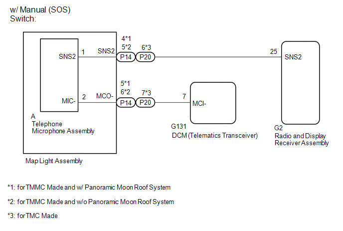
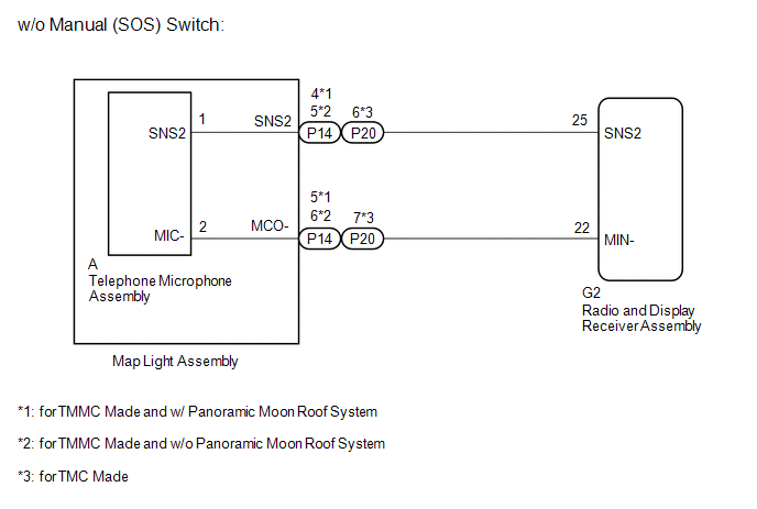
The radio and display receiver assembly, map light assembly and telephone microphone assembly are connected to each other using the microphone connection detection signal lines.
This DTC is stored when a microphone connection detection signal line is disconnected.
|
DTC No. |
Detection Item |
DTC Detection Condition |
Trouble Area |
|---|---|---|---|
|
B1579 |
Voice Recognition Microphone Disconnected |
Microphone signal is lost |
|
- *: w/ Manual (SOS) Switch
WIRING DIAGRAM
CAUTION / NOTICE / HINT
NOTICE:
-
When replacing the radio and display receiver assembly, always replace it with a new one. If a radio and display receiver assembly which was installed to another vehicle is used, the following may occur:
- A communication malfunction DTC may be stored.
- The radio and display receiver assembly may not operate normally.
-
Before replacing the DCM (telematics transceiver), refer to Registration.
for HV Model: Click here
![2020 - 2021 MY RAV4 HV [10/2019 - 12/2021]; THEFT DETERRENT / KEYLESS ENTRY: SMART KEY SYSTEM (for Start Function, HV Model): REGISTRATION](/t3Portal/stylegraphics/info.gif)
for Gasoline Model: Click here
- When replacing the DCM (telematics transceiver), make sure to replace it with a new one.
HINT:
Depending on the parts that are replaced during vehicle inspection or maintenance, performing initialization, registration or calibration may be needed. Refer to Precaution for Audio and Visual System.
Click here
PROCEDURE
|
1. |
CHECK VEHICLE TYPE |
(a) Check the vehicle type.
|
Result |
Proceed to |
|---|---|
|
for TMC Made and w/ Manual (SOS) Switch |
A |
|
for TMMC Made and w/ Manual (SOS) Switch |
B |
|
for TMC Made and w/o Manual (SOS) Switch |
C |
|
for TMMC Made and w/o Manual (SOS) Switch |
D |
| B |

|
| C |
|
| D |
|
|

|
2. |
CHECK HARNESS AND CONNECTOR (RADIO AND DISPLAY RECEIVER ASSEMBLY - MAP LIGHT ASSEMBLY) |
(a) Disconnect the G2 radio and display receiver assembly connector.
(b) Disconnect the P20 map light assembly connector.
(c) Measure the resistance according to the value(s) in the table below.
Standard Resistance:
|
Tester Connection |
Condition |
Specified Condition |
|---|---|---|
|
G2-25 (SNS2) - P20-6 (SNS2) |
Always |
Below 1 Ω |
|
G2-25 (SNS2) - Body ground |
Always |
10 kΩ or higher |
| NG |
|
REPAIR OR REPLACE HARNESS OR CONNECTOR |
|
|
3. |
CHECK HARNESS AND CONNECTOR (DCM [TELEMATICS TRANSCEIVER] - TELEPHONE MICROPHONE ASSEMBLY) |
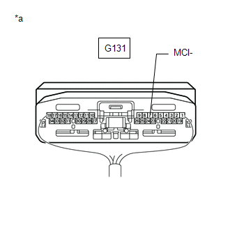
(a) Disconnect the G131 DCM (telematics transceiver) connector.
(b) Disconnect the P20 telephone microphone assembly connector.
(c) Measure the resistance according to the value(s) in the table below.
Standard Resistance:
|
Tester Connection |
Condition |
Specified Condition |
|---|---|---|
|
G131-7 (MCI-) - P20-7 (MCO-) |
Always |
Below 1 Ω |
|
G131-7 (MCI-) - Body ground |
Always |
10 kΩ or higher |
| NG |
|
REPAIR OR REPLACE HARNESS OR CONNECTOR |
|
|
4. |
CHECK DCM (TELEMATICS TRANSCEIVER) (MCI-) |
|
(a) Remove the DCM (telematics transceiver) with the connector(s) still connected. Click here
|
|
(b) Measure the resistance according to the value(s) in the table below.
Standard Resistance:
|
Tester Connection |
Condition |
Specified Condition |
|---|---|---|
|
G131-7 (MCI-) - Body ground |
Always |
Below 1 Ω |
| OK |
|
| NG |
|
|
5. |
CHECK HARNESS AND CONNECTOR (RADIO AND DISPLAY RECEIVER ASSEMBLY - MAP LIGHT ASSEMBLY) |
(a) Disconnect the G2 radio and display receiver assembly connector.
(b) Disconnect the P14 map light assembly connector.
(c) Measure the resistance according to the value(s) in the table below.
Standard Resistance:
w/ Panoramic Moon Roof System
|
Tester Connection |
Condition |
Specified Condition |
|---|---|---|
|
G2-25 (SNS2) - P14-4 (SNS2) |
Always |
Below 1 Ω |
|
G2-25 (SNS2) - Body ground |
Always |
10 kΩ or higher |
w/o Panoramic Moon Roof System
|
Tester Connection |
Condition |
Specified Condition |
|---|---|---|
|
G2-25 (SNS2) - P14-5 (SNS2) |
Always |
Below 1 Ω |
|
G2-25 (SNS2) - Body ground |
Always |
10 kΩ or higher |
| NG |
|
REPAIR OR REPLACE HARNESS OR CONNECTOR |
|
|
6. |
CHECK HARNESS AND CONNECTOR (DCM [TELEMATICS TRANSCEIVER] - TELEPHONE MICROPHONE ASSEMBLY) |
(a) Disconnect the G131 DCM (telematics transceiver) connector.
(b) Disconnect the P14 telephone microphone assembly connector.
(c) Measure the resistance according to the value(s) in the table below.
Standard Resistance:
w/ Panoramic Moon Roof System
|
Tester Connection |
Condition |
Specified Condition |
|---|---|---|
|
G131-7 (MCI-) - P14-5 (MCO-) |
Always |
Below 1 Ω |
|
G131-7 (MCI-) - Body ground |
Always |
10 kΩ or higher |
w/o Panoramic Moon Roof System
|
Tester Connection |
Condition |
Specified Condition |
|---|---|---|
|
G131-7 (MCI-) - P14-6 (MCO-) |
Always |
Below 1 Ω |
|
G131-7 (MCI-) - Body ground |
Always |
10 kΩ or higher |
| NG |
|
REPAIR OR REPLACE HARNESS OR CONNECTOR |
|
|
7. |
CHECK DCM (TELEMATICS TRANSCEIVER) (MCI-) |
|
(a) Remove the DCM (telematics transceiver) with the connector(s) still connected. Click here
|
|
(b) Measure the resistance according to the value(s) in the table below.
Standard Resistance:
|
Tester Connection |
Condition |
Specified Condition |
|---|---|---|
|
G131-7 (MCI-) - Body ground |
Always |
Below 1 Ω |
| OK |
|
| NG |
|
|
8. |
CHECK HARNESS AND CONNECTOR (RADIO AND DISPLAY RECEIVER ASSEMBLY - MAP LIGHT ASSEMBLY) |
(a) Disconnect the G2 radio and display receiver assembly connector.
(b) Disconnect the P20 map light assembly connector.
(c) Measure the resistance according to the value(s) in the table below.
Standard Resistance:
|
Tester Connection |
Condition |
Specified Condition |
|---|---|---|
|
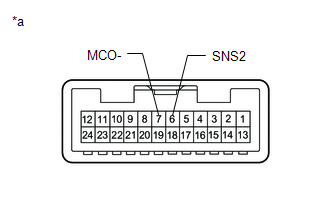
G2-25 (SNS2) - P20-6 (SNS2) |
Always |
Below 1 Ω |
|
G2-22 (MIN-) - P20-7 (MCO-) |
Always |
Below 1 Ω |
|
G2-25 (SNS2) - Body ground |
Always |
10 kΩ or higher |
|
G2-22 (MIN-) - Body ground |
Always |
10 kΩ or higher |
| NG |
|
REPAIR OR REPLACE HARNESS OR CONNECTOR |
|
|
9. |
INSPECT MAP LIGHT ASSEMBLY |
|
(a) Remove the map light assembly. Click here
|
|
(b) Measure the resistance according to the value(s) in the table below.
Standard Resistance:
|
Tester Connection |
Condition |
Specified Condition |
|---|---|---|
|
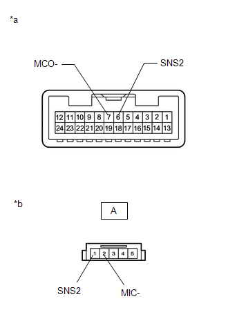
6 (SNS2) - 7 (MCO-) |
Always |
Below 1 Ω |
| OK |
|
|
|
10. |
INSPECT MAP LIGHT ASSEMBLY |
|
(a) Remove the map light assembly. Click here
|
|
(b) Disconnect the telephone microphone assembly connector.
(c) Measure the resistance according to the value(s) in the table below.
Standard Resistance:
|
Tester Connection |
Condition |
Specified Condition |
|---|---|---|
|
6 (SNS2) - A-1 (SNS2) |
Always |
Below 1 Ω |
|
7 (MCO-) - A-2 (MIC-) |
Always |
Below 1 Ω |
| OK |
|
REPLACE TELEPHONE MICROPHONE ASSEMBLY
|
| NG |
|
|
11. |
CHECK HARNESS AND CONNECTOR (RADIO AND DISPLAY RECEIVER ASSEMBLY - MAP LIGHT ASSEMBLY) |
(a) Disconnect the G2 radio and display receiver assembly connector.
(b) Disconnect the P14 map light assembly connector.
(c) Measure the resistance according to the value(s) in the table below.
Standard Resistance:
w/ Panoramic Moon Roof System
|
Tester Connection |
Condition |
Specified Condition |
|---|---|---|
|
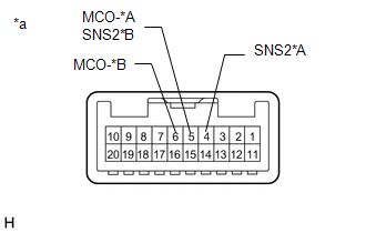
G2-25 (SNS2) - P14-4 (SNS2) |
Always |
Below 1 Ω |
|
G2-22 (MIN-) - P14-5 (MCO-) |
Always |
Below 1 Ω |
|
G2-25 (SNS2) - Body ground |
Always |
10 kΩ or higher |
|
G2-22 (MIN-) - Body ground |
Always |
10 kΩ or higher |
w/o Panoramic Moon Roof System
|
Tester Connection |
Condition |
Specified Condition |
|---|---|---|
|
G2-25 (SNS2) - P14-5 (SNS2) |
Always |
Below 1 Ω |
|
G2-22 (MIN-) - P14-6 (MCO-) |
Always |
Below 1 Ω |
|
G2-25 (SNS2) - Body ground |
Always |
10 kΩ or higher |
|
G2-22 (MIN-) - Body ground |
Always |
10 kΩ or higher |
| NG |
|
REPAIR OR REPLACE HARNESS OR CONNECTOR |
|
|
12. |
INSPECT MAP LIGHT ASSEMBLY |
|
(a) Remove the map light assembly. Click here
|
|
(b) Measure the resistance according to the value(s) in the table below.
Standard Resistance:
w/ Panoramic Moon Roof System
|
Tester Connection |
Condition |
Specified Condition |
|---|---|---|
|
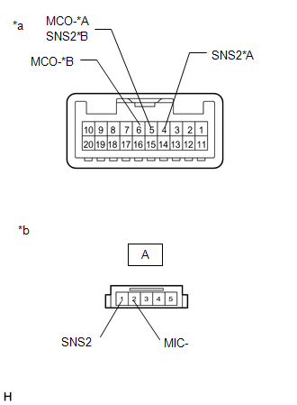
4 (SNS2) - 5 (MCO-) |
Always |
Below 1 Ω |
w/o Panoramic Moon Roof System
|
Tester Connection |
Condition |
Specified Condition |
|---|---|---|
|
5 (SNS2) - 6 (MCO-) |
Always |
Below 1 Ω |
| OK |
|
|
|
13. |
INSPECT MAP LIGHT ASSEMBLY |
|
(a) Remove the map light assembly. Click here
|
|
(b) Disconnect the telephone microphone assembly connector.
(c) Measure the resistance according to the value(s) in the table below.
Standard Resistance:
w/ Panoramic Moon Roof System
|
Tester Connection |
Condition |
Specified Condition |
|---|---|---|
|
4 (SNS2) - A-1 (SNS2) |
Always |
Below 1 Ω |
|
5 (MCO-) - A-2 (MIC-) |
Always |
Below 1 Ω |
w/o Panoramic Moon Roof System
|
Tester Connection |
Condition |
Specified Condition |
|---|---|---|
|
5 (SNS2) - A-1 (SNS2) |
Always |
Below 1 Ω |
|
6 (MCO-) - A-2 (MIC-) |
Always |
Below 1 Ω |
| OK |
|
REPLACE TELEPHONE MICROPHONE ASSEMBLY
|
| NG |
|
|
|
|