| Last Modified: 02-14-2025 | 6.11:8.1.0 | Doc ID: RM100000001LR9U |
| Model Year Start: 2020 | Model: RAV4 | Prod Date Range: [10/2019 - 10/2022] |
| Title: CELLULAR COMMUNICATION: TOYOTA AUDIO MULTIMEDIA SYSTEM: DCM Data Signal Circuit between Radio Receiver and DCM; 2020 - 2022 MY RAV4 RAV4 HV [10/2019 - 10/2022] | ||
|
DCM Data Signal Circuit between Radio Receiver and DCM |
DESCRIPTION
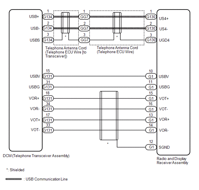
This circuit is used to send and receive signals between the DCM (telephone transceiver assembly) and radio and display receiver assembly.
WIRING DIAGRAM
PROCEDURE
|
1. |
CHECK HARNESS AND CONNECTOR (RADIO AND DISPLAY RECEIVER ASSEMBLY - DCM [TELEPHONE TRANSCEIVER ASSEMBLY]) |
(a) Disconnect the G1 radio and display receiver assembly connector.
(b) Disconnect the G131 DCM (telephone transceiver assembly) connector.
(c) Measure the resistance according to the value(s) in the table below.
Standard Resistance:
|
Tester Connection |
Condition |
Specified Condition |
|---|---|---|
|
G1-10 (USBV) - G131-15 (USBV) |
Always |
Below 1 Ω |
|
G1-11 (USBG) - G131-31 (USBG) |
Always |
Below 1 Ω |
|
G1-15 (VOT+) - G131-18 (VOR+) |
Always |
Below 1 Ω |
|
G1-16 (VOT-) - G131-34 (VOR-) |
Always |
Below 1 Ω |
|
G1-13 (VOR+) - G131-17 (VOT+) |
Always |
Below 1 Ω |
|
G1-14 (VOR-) - G131-33 (VOT-) |
Always |
Below 1 Ω |
|
G1-10 (USBV) - Body ground |
Always |
10 kΩ or higher |
|
G1-11 (USBG) - Body ground |
Always |
10 kΩ or higher |
|
G1-15 (VOT+) - Body ground |
Always |
10 kΩ or higher |
|
G1-16 (VOT-) - Body ground |
Always |
10 kΩ or higher |
|
G1-13 (VOR+) - Body ground |
Always |
10 kΩ or higher |
|
G1-14 (VOR-) - Body ground |
Always |
10 kΩ or higher |
|
G1-12 (SGND) - Body ground |
Always |
10 kΩ or higher |
| NG |

|
REPAIR OR REPLACE HARNESS OR CONNECTOR |
|

|
2. |
CHECK TELEPHONE ANTENNA CORD (TELEPHONE ECU WIRE [TO TRANSCEIVER]) |
|
(a) Disconnect the G134 telephone antenna cord (telephone ECU wire [to transceiver]) connector from the DCM (telephone transceiver assembly). |
|
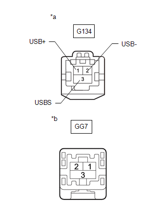
(b) Disconnect the GG7 telephone antenna cord (telephone ECU wire [to transceiver]) connector from the telephone antenna cord (telephone ECU wire).
(c) Measure the resistance according to the value(s) in the table below.
Standard Resistance:
|
Tester Connection |
Condition |
Specified Condition |
|---|---|---|
|
G134-1 (USB+) - GG7-1 |
Always |
Below 1 Ω |
|
G134-2 (USB-) - GG7-2 |
Always |
Below 1 Ω |
|
G134-3 (USBS) - GG7-3 |
Always |
Below 1 Ω |
|
G134-1 (USB+) - Body ground |
Always |
10 kΩ or higher |
|
G134-2 (USB-) - Body ground |
Always |
10 kΩ or higher |
|
G134-3 (USBS) - Body ground |
Always |
10 kΩ or higher |
| NG |
|
REPLACE TELEPHONE ANTENNA CORD (TELEPHONE ECU WIRE [TO TRANSCEIVER]) |
|
|
3. |
CHECK TELEPHONE ANTENNA CORD (TELEPHONE ECU WIRE) |
|
(a) Disconnect the G130 telephone antenna cord (telephone ECU wire) connector from the radio and display receiver assembly. |
|
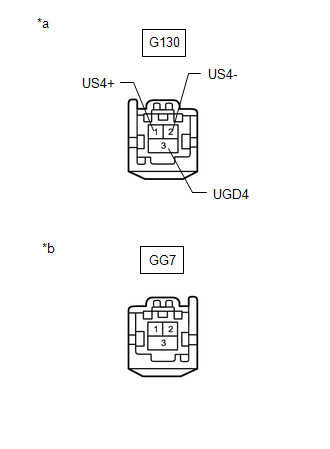
(b) Disconnect the GG7 telephone antenna cord (telephone ECU wire) connector from the telephone antenna cord (telephone ECU wire [to transceiver]).
(c) Measure the resistance according to the value(s) in the table below.
Standard Resistance:
|
Tester Connection |
Condition |
Specified Condition |
|---|---|---|
|
G130-1 (US4+) - GG7-1 |
Always |
Below 1 Ω |
|
G130-2 (US4-) - GG7-2 |
Always |
Below 1 Ω |
|
G130-3 (UGD4) - GG7-3 |
Always |
Below 1 Ω |
|
G130-2 (US4+) - Body ground |
Always |
10 kΩ or higher |
|
G130-1 (US4-) - Body ground |
Always |
10 kΩ or higher |
|
G130-3 (UGD4) - Body ground |
Always |
10 kΩ or higher |
| OK |
|
PROCEED TO NEXT SUSPECTED AREA SHOWN IN PROBLEM SYMPTOMS TABLE |
| NG |
|
|
|
|