| Last Modified: 01-30-2024 | 6.11:8.1.0 | Doc ID: RM100000001KJOU |
| Model Year Start: 2020 | Model: RAV4 | Prod Date Range: [10/2019 - 12/2021] |
| Title: BRAKE CONTROL / DYNAMIC CONTROL SYSTEMS: ELECTRONICALLY CONTROLLED BRAKE SYSTEM (w/o Vacuum Brake Booster): C1380; Stop Light Control Relay Malfunction; 2020 - 2021 MY RAV4 RAV4 HV [10/2019 - 12/2021] | ||
|
DTC |
C1380 |
Stop Light Control Relay Malfunction |
DESCRIPTION
When any of the following conditions are met, the skid control ECU (brake booster with master cylinder assembly) sets the drive output (STPO) ON which operates the stop light control relay (stop light switch assembly) and turns on the stop lights.
Illumination Conditions:
- Pre-collision brake is operating.*
- The dynamic radar cruise control system is operating and is applying the brakes.*
- Secondary collision brake is operating.
- Brake hold is operating.
- The parking brake is engaged while the vehicle is being driven.
- *: w/ Pre-collision System
|
DTC No. |
Detection Item |
INF Code |
DTC Detection Condition |
Trouble Area |
Note |
|---|---|---|---|---|---|
|
C1380 |
Stop Light Control Relay Malfunction |
761 762 |
|
|
- |
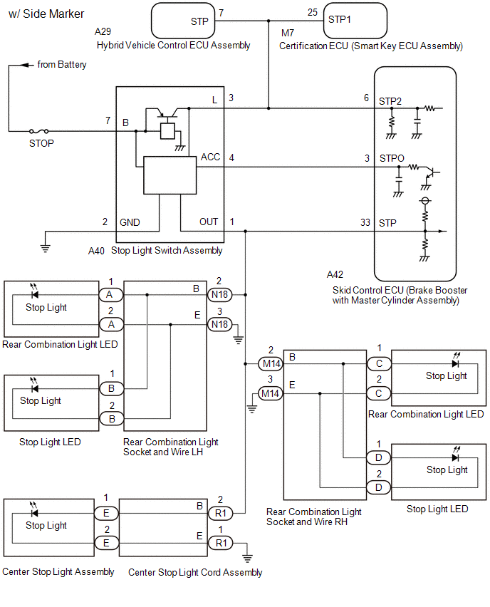
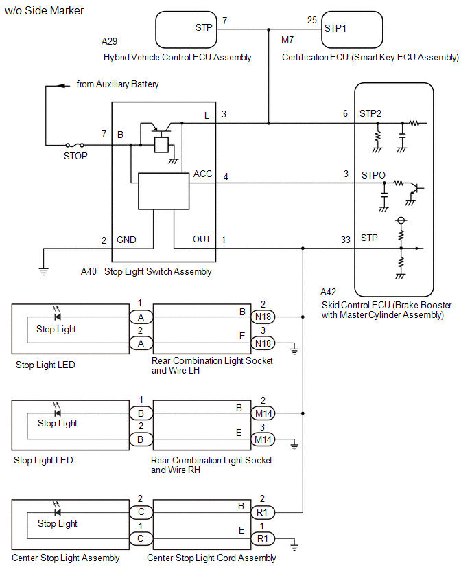
WIRING DIAGRAM
CAUTION / NOTICE / HINT
NOTICE:
-
When replacing the skid control ECU (brake booster with master cylinder assembly), perform initialization and calibration of the linear solenoid valve.
Click here
Click here
![2019 - 2021 MY RAV4 RAV4 HV [02/2019 - 12/2021]; BRAKE CONTROL / DYNAMIC CONTROL SYSTEMS: ELECTRONICALLY CONTROLLED BRAKE SYSTEM (w/o Vacuum Brake Booster): UTILITY](/t3Portal/stylegraphics/info.gif)
- Inspect the fuses for circuits related to this system before performing the following procedure.
-
If the certification ECU (smart key ECU assembly) is replaced, refer to Registration.
Click here
HINT:
When C1249 is output together with C1380, inspect and repair the trouble areas indicated by C1249 first.
Click here
PROCEDURE
|
1. |
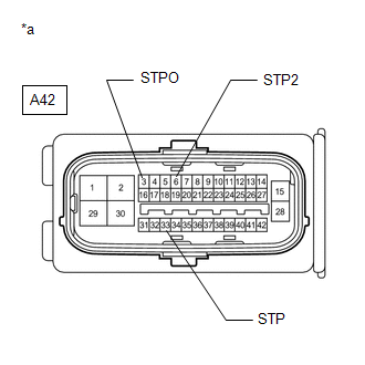
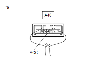
CHECK HARNESS AND CONNECTOR (STP, STPO AND STP2 TERMINAL) |
|
(a) Turn the ignition switch off. |
|
(b) Make sure that there is no looseness at the locking part and the connecting part of the connector.
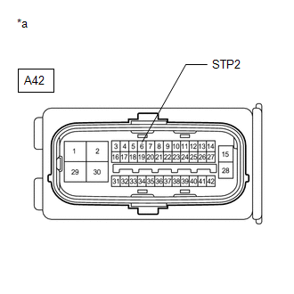
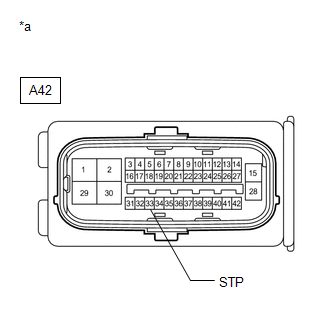
(c) Disconnect the A42 skid control ECU (brake booster with master cylinder assembly) connector.
(d) Measure the voltage according to the value(s) in the table below.
Standard Voltage:
|
Tester Connection |
Condition |
Specified Condition |
|---|---|---|
|
A42-33 (STP) - Body ground |
Stop light switch assembly on (Brake pedal depressed) |
11 to 14 V |
|
A42-33 (STP) - Body ground |
Stop light switch assembly off (Brake pedal released) |
Below 1.5 V |
|
A42-3 (STPO) - Body ground |
Always |
11 to 14 V |
|
A42-6 (STP2) - Body ground |
Stop light switch assembly on (Brake pedal depressed) |
11 to 14 V |
|
A42-6 (STP2) - Body ground |
Stop light switch assembly off (Brake pedal released) |
Below 1.5 V |
|
Result |
Proceed to |
|---|---|
|
All terminal voltages are normal. |
A |
|
Only STP2 terminal voltage abnormal. |
B |
|
Only STPO terminal voltage abnormal. |
C |
|
Only STP terminal voltage abnormal. (w/ Side Marker) |
D |
|
Only STP terminal voltage abnormal. (w/o Side Marker) |
E |
|
STPO terminal and STP terminal voltage abnormal. |
F |
| B |

|
| C |
|
| D |
|
| E |
|
| F |
|
|

|
2. |
PERFORM ACTIVE TEST USING TECHSTREAM (STOP LIGHT RELAY) |
(a) Reconnect the A42 skid control ECU (brake booster with master cylinder assembly) connector.
(b) Select the Active Test on the Techstream.
Click here
Chassis > ABS/VSC/TRAC > Active Test
|
Tester Display |
Measurement Item |
Control Range |
Diagnostic Note |
|---|---|---|---|
|
Stop Light Relay |
Stop light switch assembly (stop light control relay) |
Stop light switch assembly (Relay) ON/OFF |
Stop lights come on |
Chassis > ABS/VSC/TRAC > Active Test
|
Tester Display |
|---|
|
Stop Light Relay |
(c) According to the display on the Techstream, perform the Active Test and check the operation of the stop lights.
OK:
Stop lights turn on/off in accordance with the Active Test.
| NG |
|
|
|
3. |
RECONFIRM DTC |
(a) Clear the DTCs.
Click here
Chassis > ABS/VSC/TRAC > Clear DTCs
(b) Select the Active Test on the Techstream.
Click here
Chassis > ABS/VSC/TRAC > Active Test
|
Tester Display |
Measurement Item |
Control Range |
Diagnostic Note |
|---|---|---|---|
|
Stop Light Relay |
Stop light switch assembly (stop light control relay) |
Stop light switch assembly (Relay) ON/OFF |
Stop lights come on |
Chassis > ABS/VSC/TRAC > Active Test
|
Tester Display |
|---|
|
Stop Light Relay |
(c) According to the display on the Techstream, perform the Active Test.
(d) Check if the same DTC is output.
Click here
Chassis > ABS/VSC/TRAC > Trouble Codes
|
Result |
Proceed to |
|---|---|
|
DTC C1380 is output. |
A |
|
DTC C1380 is not output. |
B |
| A |
|
REPLACE BRAKE BOOSTER WITH MASTER CYLINDER ASSEMBLY
|
| B |
|
|
4. |
INSPECT BRAKE BOOSTER WITH MASTER CYLINDER ASSEMBLY |
(a) Select the Active Test on the Techstream.
Click here
Chassis > ABS/VSC/TRAC > Active Test
|
Tester Display |
Measurement Item |
Control Range |
Diagnostic Note |
|---|---|---|---|
|
Stop Light Relay |
Stop light switch assembly (stop light control relay) |
Stop light switch assembly (Relay) ON/OFF |
Stop lights come on |
Chassis > ABS/VSC/TRAC > Active Test
|
Tester Display |
|---|
|
Stop Light Relay |
|
(b) Measure the voltage according to the value(s) in the table below. Standard Voltage:
|
|
| OK |
|
| NG |
|
REPLACE BRAKE BOOSTER WITH MASTER CYLINDER ASSEMBLY
|
|
5. |
CHECK HARNESS AND CONNECTOR (BRAKE BOOSTER WITH MASTER CYLINDER ASSEMBLY - HYBRID VEHICLE CONTROL ECU ASSEMBLY) |
(a) Disconnect the A29 hybrid vehicle control ECU assembly connector.
|
(b) Measure the voltage according to the value(s) in the table below. Standard Voltage:
|
|
| OK |
|
REPLACE HYBRID VEHICLE CONTROL ECU ASSEMBLY
|
|
|
6. |
CHECK HARNESS AND CONNECTOR (BRAKE BOOSTER WITH MASTER CYLINDER ASSEMBLY - SMART KEY ECU ASSEMBLY) |
(a) Disconnect the M7 certification ECU (smart key ECU assembly) connector.
|
(b) Measure the voltage according to the value(s) in the table below. Standard Voltage:
|
|
| OK |
|
REPLACE SMART KEY ECU ASSEMBLY
|
|
|
7. |
CHECK HARNESS AND CONNECTOR (BRAKE BOOSTER WITH MASTER CYLINDER ASSEMBLY - STOP LIGHT SWITCH ASSEMBLY) |
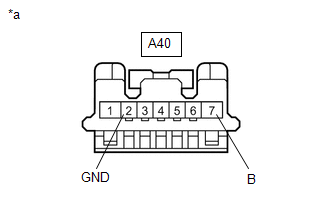
(a) Disconnect the A40 stop light switch assembly connector.
|
(b) Measure the voltage according to the value(s) in the table below. Standard Voltage:
|
|
| NG |
|
REPAIR OR REPLACE HARNESS OR CONNECTOR |
|
|
8. |
CHECK HARNESS AND CONNECTOR (BRAKE BOOSTER WITH MASTER CYLINDER ASSEMBLY - STOP LIGHT SWITCH ASSEMBLY) |
(a) Measure the resistance according to the value(s) in the table below.
Standard Resistance:
|
Tester Connection |
Condition |
Specified Condition |
|---|---|---|
|
A42-6 (STP2) - A40-3 (L) |
Always |
Below 1 Ω |
|
A42-6 (STP2) or A40-3 (L) - Body ground |
Always |
10 kΩ or higher |
| OK |
|
| NG |
|
REPAIR OR REPLACE HARNESS OR CONNECTOR |
|
9. |
CHECK HARNESS AND CONNECTOR (BRAKE BOOSTER WITH MASTER CYLINDER ASSEMBLY - STOP LIGHT SWITCH ASSEMBLY) |
(a) Disconnect the A40 stop light switch assembly connector.
(b) Measure the resistance according to the value(s) in the table below.
Standard Resistance:
|
Tester Connection |
Condition |
Specified Condition |
|---|---|---|
|
A42-3 (STPO) - A40-4 (ACC) |
Always |
Below 1 Ω |
| OK |
|
| NG |
|
REPAIR OR REPLACE HARNESS OR CONNECTOR |
|
10. |
CHECK HARNESS AND CONNECTOR (BRAKE BOOSTER WITH MASTER CYLINDER ASSEMBLY - REAR COMBINATION LIGHT SOCKET AND WIRE LH) |
(a) Disconnect the N18 rear combination light socket and wire LH connector.
|
(b) Measure the voltage according to the value(s) in the table below. Standard Voltage:
|
|
| NG |
|
|
|
11. |
CHECK HARNESS AND CONNECTOR (BRAKE BOOSTER WITH MASTER CYLINDER ASSEMBLY - REAR COMBINATION LIGHT SOCKET AND WIRE LH) |
(a) Reconnect the N18 rear combination light socket and wire LH connector.
(b) Disconnect the B stop light LED connector.
|
(c) Measure the voltage according to the value(s) in the table below. Standard Voltage:
|
|
| OK |
|
|
|
12. |
CHECK HARNESS AND CONNECTOR (BRAKE BOOSTER WITH MASTER CYLINDER ASSEMBLY - REAR COMBINATION LIGHT SOCKET AND WIRE LH) |
(a) Disconnect the A rear combination light LED connector.
|
(b) Measure the voltage according to the value(s) in the table below. Standard Voltage:
|
|
| OK |
|
| NG |
|
|
13. |
CHECK HARNESS AND CONNECTOR (BRAKE BOOSTER WITH MASTER CYLINDER ASSEMBLY - REAR COMBINATION LIGHT SOCKET AND WIRE RH) |
(a) Disconnect the M14 rear combination light socket and wire RH connector.
|
(b) Measure the voltage according to the value(s) in the table below. Standard Voltage:
|
|
| NG |
|
|
|
14. |
CHECK HARNESS AND CONNECTOR (BRAKE BOOSTER WITH MASTER CYLINDER ASSEMBLY - REAR COMBINATION LIGHT SOCKET AND WIRE RH) |
(a) Reconnect the M14 rear combination light socket and wire RH connector.
(b) Disconnect the D stop light LED connector.
|
(c) Measure the voltage according to the value(s) in the table below. Standard Voltage:
|
|
| OK |
|
|
|
15. |
CHECK HARNESS AND CONNECTOR (BRAKE BOOSTER WITH MASTER CYLINDER ASSEMBLY - REAR COMBINATION LIGHT SOCKET AND WIRE RH) |
(a) Disconnect the C rear combination light LED connector.
|
(b) Measure the voltage according to the value(s) in the table below. Standard Voltage:
|
|
| OK |
|
| NG |
|
|
16. |
CHECK HARNESS AND CONNECTOR (BRAKE BOOSTER WITH MASTER CYLINDER ASSEMBLY - CENTER STOP LIGHT ASSEMBLY) |
(a) Disconnect the E center stop light assembly connector.
|
(b) Measure the voltage according to the value(s) in the table below. Standard Voltage:
|
|
| OK |
|
| NG |
|
|
17. |
CHECK HARNESS AND CONNECTOR (BRAKE BOOSTER WITH MASTER CYLINDER ASSEMBLY - STOP LIGHT LED) |
(a) Disconnect the A stop light LED connector.
|
(b) Measure the voltage according to the value(s) in the table below. Standard Voltage:
|
|
| OK |
|
|
|
18. |
CHECK HARNESS AND CONNECTOR (BRAKE BOOSTER WITH MASTER CYLINDER ASSEMBLY - REAR COMBINATION LIGHT SOCKET AND WIRE LH) |
(a) Disconnect the N18 rear combination light socket and wire LH connector.
|
(b) Measure the voltage according to the value(s) in the table below. Standard Voltage:
|
|
| OK |
|
|
|
19. |
CHECK HARNESS AND CONNECTOR (BRAKE BOOSTER WITH MASTER CYLINDER ASSEMBLY - STOP LIGHT LED) |
(a) Disconnect the B stop light LED connector.
|
(b) Measure the voltage according to the value(s) in the table below. Standard Voltage:
|
|
| OK |
|
|
|
20. |
CHECK HARNESS AND CONNECTOR (BRAKE BOOSTER WITH MASTER CYLINDER ASSEMBLY - REAR COMBINATION LIGHT SOCKET AND WIRE RH) |
(a) Disconnect the M14 rear combination light socket and wire RH connector.
|
(b) Measure the voltage according to the value(s) in the table below. Standard Voltage:
|
|
| OK |
|
| NG |
|
|
21. |
CHECK STOP LIGHT SWITCH ASSEMBLY POWER SOURCE CIRCUIT |
(a) Disconnect the A40 stop light switch assembly connector.
|
(b) Measure the voltage according to the value(s) in the table below. Standard Voltage:
|
|
(c) Measure the resistance according to the value(s) in the table below.
Standard Resistance:
|
Tester Connection |
Condition |
Specified Condition |
|---|---|---|
|
A40-2 (GND) - Body ground |
Always |
Below 1 Ω |
| NG |
|
REPAIR OR REPLACE HARNESS OR CONNECTOR |
|
|
22. |
CHECK HARNESS AND CONNECTOR (BRAKE BOOSTER WITH MASTER CYLINDER ASSEMBLY - STOP LIGHT SWITCH ASSEMBLY) |
(a) Measure the resistance according to the value(s) in the table below.
Standard Resistance:
|
Tester Connection |
Condition |
Specified Condition |
|---|---|---|
|
A42-3 (STPO) or A40-4 (ACC) - Body ground |
Always |
10 kΩ or higher |
| OK |
|
| NG |
|
REPAIR OR REPLACE HARNESS OR CONNECTOR |
|
23. |
CHECK HARNESS AND CONNECTOR (BRAKE BOOSTER WITH MASTER CYLINDER ASSEMBLY - CENTER STOP LIGHT ASSEMBLY) |
(a) Disconnect the C center stop light assembly connector.
|
(b) Measure the voltage according to the value(s) in the table below. Standard Voltage:
|
|
| OK |
|
|
|
24. |
CHECK HARNESS AND CONNECTOR (BRAKE BOOSTER WITH MASTER CYLINDER ASSEMBLY - CENTER STOP LIGHT CORD ASSEMBLY) |
(a) Disconnect the R1 center stop light cord assembly connector.
|
(b) Measure the voltage according to the value(s) in the table below. Standard Voltage:
|
|
| OK |
|
|
|
25. |
CHECK HARNESS AND CONNECTOR (BRAKE BOOSTER WITH MASTER CYLINDER ASSEMBLY - STOP LIGHT SWITCH ASSEMBLY) |
|
(a) Disconnect the A40 stop light switch assembly connector. |
|
(b) Measure the voltage according to the value(s) in the table below.
Standard Voltage:
|
Tester Connection |
Condition |
Specified Condition |
|---|---|---|
|
A42-33 (STP) - Body ground |
Always |
1.5 V or less |
| NG |
|
REPAIR OR REPLACE HARNESS OR CONNECTOR |
|
|
26. |
CHECK HARNESS AND CONNECTOR (BRAKE BOOSTER WITH MASTER CYLINDER ASSEMBLY - STOP LIGHT SWITCH ASSEMBLY) |
(a) Measure the resistance according to the value(s) in the table below.
Standard Resistance:
|
Tester Connection |
Condition |
Specified Condition |
|---|---|---|
|
A40-1 (OUT) - A42-33 (STP) |
Always |
Below 1 Ω |
|
A40-1 (OUT) or A42-33 (STP) - Body ground |
Always |
10 kΩ or higher |
| OK |
|
| NG |
|
REPAIR OR REPLACE HARNESS OR CONNECTOR |
|
|
|