| Last Modified: 11-18-2025 | 6.11:8.1.0 | Doc ID: RM100000001KGA7 |
| Model Year Start: 2020 | Model: RAV4 | Prod Date Range: [10/2019 - 10/2022] |
| Title: AUDIO / VIDEO: AUDIO AND VISUAL SYSTEM: TERMINALS OF ECU; 2020 - 2022 MY RAV4 RAV4 HV [10/2019 - 10/2022] | ||
TERMINALS OF ECU
HINT:
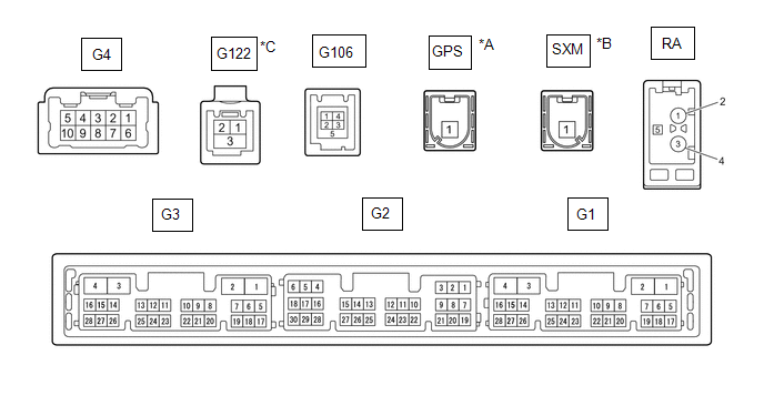
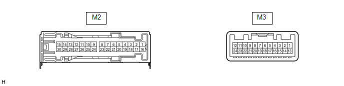
Check from the rear of the connector while it is connected to the components.
RADIO AND DISPLAY RECEIVER ASSEMBLY
|
*A |
w/ GPS Function |
*B |
w/ SXM Function |
|
*C |
w/ GPS Function and w/ Manual (SOS) Switch |
- |
- |
|
Terminal No. (Symbol) |
Wiring Color |
Terminal Description |
Condition |
Specified Condition |
|---|---|---|---|---|
|
G4-1 (FR+) - G3-1 (GND1) |
LA-LG - W-B*1 W - W-B*2 |
Sound signal (Front right)*1 Sound signal (Right)*2 |
Audio system playing |
A waveform synchronized with sound signals is output |
|
G4-2 (FL+) - G3-1 (GND1) |
LA-B - W-B*1 B - W-B*2 |
Sound signal (Front left)*1 Sound signal (Left)*2 |
Audio system playing |
A waveform synchronized with sound signals is output |
|
G4-3 (RL+) - G3-1 (GND1) |
LA-G - W-B*1 Y - W-B*2 |
Sound signal (Rear left)*1 Voice signal*2 |
Audio system playing*1 Voice guidance sounding*2 |
A waveform synchronized with sound signals is output*1 A waveform synchronized with voice signals is output*2 |
|
G4-4 (RR+) - G3-1 (GND1)*1 |
LA-R - W-B |
Sound signal (Rear right) |
Audio system playing |
A waveform synchronized with sound signals is output |
|
G4-6 (FR-) - G3-1 (GND1) |
LA-L - W-B*1 R - W-B*2 |
Sound signal (Front right)*1 Sound signal (Right)*2 |
Audio system playing |
A waveform synchronized with sound signals is output |
|
G4-7 (FL-) - G3-1 (GND1) |
LA-R - W-B*1 G - W-B*2 |
Sound signal (Front left)*1 Sound signal (Left)*2 |
Audio system playing |
A waveform synchronized with sound signals is output |
|
G4-8 (RL-) - G3-1 (GND1) |
LA-GR - W-B*1 BR - W-B*2 |
Sound signal (Rear left)*1 Voice signal*2 |
Audio system playing*1 Voice guidance sounding*2 |
A waveform synchronized with sound signals is output*1 A waveform synchronized with voice signals is output*2 |
|
G4-9 (RR-) - G3-1 (GND1)*1 |
LA-G - W-B |
Sound signal (Rear right) |
Audio system playing |
A waveform synchronized with sound signals is output |
|
G3-1 (GND1) - Body ground |
W-B - Body ground |
Ground |
Always |
Below 1 Ω |
|
G3-4 (+B1) - G3-1 (GND1) |
BE - W-B*11 LG - W-B*12 |
Power source (+B) |
Ignition switch off |
10.5 to 16 V*11 11 to 14 V*12 |
|
G3-5 (TX1+)*2 |
B |
AVC-LAN communication signal |
- |
- |
|
G3-6 (TX1-)*2 |
W |
AVC-LAN communication signal |
- |
- |
|
G3-15 (ACC1) - G3-1 (GND1) |
GR - W-B |
Power source (ACC) |
Ignition switch off |
Below 1 V |
|
Ignition switch ACC |
10.5 to 16 V*11 11 to 14 V*12 |
|||
|
G3-21 (SW1) - G3-24 (SWG) |
W - W-B |
Steering pad switch signal |
No switch pushed |
2.97 to 3.56 V |
|
Seek+ switch pushed |
0.27 to 0.35 V |
|||
|
Seek- switch pushed |
0.86 to 1.03 V |
|||
|
Volume+ switch pushed |
1.51 to 1.79 V |
|||
|
Volume- switch pushed |
2.22 to 2.66 V |
|||
|
G3-22 (SW2) - G3-24 (SWG) |
LG - W-B |
Steering pad switch signal |
No switch pushed |
2.97 to 3.56 V |
|
MODE switch pushed |
0.27 to 0.35 V |
|||
|
Telephone switch pushed |
1.51 to 1.79 V |
|||
|
Voice switch pushed |
2.22 to 2.66 V |
|||
|
G3-24 (SWG) - G3-1 (GND1) |
W-B - W-B |
Steering pad switch ground |
Always |
Below 1 Ω |
|
G3-25 (MUT1) - G3-1 (GND1)*2 |
BE - W-B |
Mute signal |
Audio system playing |
2.0 V or higher |
|
Audio system changing modes |
Below 1 V |
|||
|
G3-27 (SPD) - G3-1 (GND1) |
LG - W-B |
Vehicle speed signal |
See "Check Vehicle Signal" in Operation Check Click here
|
- |
|
G3-28 (REV) - G3-1 (GND1) |
W - W-B |
Reverse signal |
See "Check Vehicle Signal" in Operation Check Click here
|
- |
|
G2-3 (TMUT) - G3-1 (GND1)*3 |
BE - W-B |
Mute signal |
Audio system playing |
Above 2.0 V |
|
Emergency call mode |
Below 1 V |
|||
|
G2-5 (CNH1)*9 |
L |
Local bus communication signal |
- |
- |
|
G2-6 (CNL1)*9 |
W |
Local bus communication signal |
- |
- |
|
G2-13 (CANH) |
B |
CAN communication signal |
- |
- |
|
G2-14 (CANL) |
W |
CAN communication signal |
- |
- |
|
G2-15 (ILL+) - G3-1 (GND1) |
G - W-B |
Illumination signal |
Light control switch off |
Below 1 V |
|
Light control switch in tail or head position |
11 to 14 V |
|||
|
G2-16 (ILL-) - G3-1 (GND1) |
BE - W-B |
Illumination signal |
Light control switch off |
Below 1 V |
|
Light control switch in tail or head position |
Pulse generation |
|||
|
G2-18 (CSW+) - G3-1 (GND1)*4 |
L - W-B |
Camera image change signal |
Ignition switch ACC, shift position not in R →in R |
3.5 V or higher → Below 1 V |
|
G2-19 (IG) - G3-1 (GND1) |
W - W-B |
Power source (IG) |
Ignition switch off |
Below 1 V |
|
Ignition switch ON |
11 to 14 V |
|||
|
G2-20 (PKB) - G3-1 (GND1) |
B - W-B |
Parking brake signal |
See "Check Vehicle Signal" in Operation Check Click here
|
- |
|
G2-21 (MIN+) - G3-1 (GND1) |
W - W-B*5 SB - W-B*8 |
Microphone voice signal |
See "Check Microphone" in Operation Check Click here
|
- |
|
G2-22 (MIN-) - G3-1 (GND1) |
R - W-B*5 V - W-B*8 |
Microphone voice signal |
See "Check Microphone" in Operation Check Click here
|
- |
|
G2-23 (MACC) - G3-1 (GND1)*5 |
B - W-B |
Microphone power supply |
Ignition switch off |
Below 1 V |
|
Ignition switch ACC |
4 to 6 V |
|||
|
G2-24 (SGND) - Body ground |
Shielded - Body ground |
Shield ground |
Always |
Below 1 Ω |
|
G2-25 (SNS2) - G3-1 (GND1) |
BE - W-B |
Microphone connection detection signal |
Always |
Below 1 V |
|
G2-26 (CSLD) - Body ground*6 |
Shielded - Body ground |
Shield ground |
Always |
Below 1 Ω |
|
G2-27 (CGND) - Body ground*6 |
G - Body ground |
Camera ground |
Always |
Below 1 Ω |
|
G2-28 (V+) - G2-29 (V-)*7 |
V - SB*4 B - W*6 |
Video signal |
Ignition switch ON, Shift position in R Camera lens not covered, displaying image |
Pulse generation (Refer to waveform 1) |
|
Ignition switch ON, Shift position in R Camera lens covered, blacking out screen |
Pulse generation (Refer to waveform 2) |
|||
|
G2-29 (V-) - Body ground*7 |
SB - Body ground*4 W - Body ground*6 |
Video signal ground |
Always |
Below 1 Ω |
|
G2-30 (CA+) - Body ground*6 |
R - Body ground |
Power source |
Ignition switch ACC |
5.5 to 7.05 V |
|
G1-10 (USBV) - Body ground*8 |
L - Body ground |
DCM (telematics transceiver) power supply |
Ignition switch off |
Below 1 V |
|
Ignition switch ACC |
4.75 to 5.25 V |
|||
|
G1-11 (USBG) - Body ground*8 |
GR - Body ground |
Ground |
Always |
Below 1 Ω |
|
G1-12 (SGND) - Body ground*8 |
Shielded - Body ground |
Shield ground |
Always |
Below 1 Ω |
|
G1-13 (VOR+) - G3-1 (GND1)*8 |
R - W-B |
Receive voice signal |
Destination assist service in use and operator speaking to vehicle occupant |
A waveform synchronized with the received voice is output. |
|
G1-14 (VOR-) - G3-1 (GND1)*8 |
G - W-B |
Receive voice signal |
Destination assist service in use and operator speaking to vehicle occupant |
A waveform synchronized with the received voice is output. |
|
G1-15 (VOT+) - G3-1 (GND1)*8 |
B - W-B |
Sent voice signal |
Destination assist service in use and operator speaking to vehicle occupant |
A waveform synchronized with the received voice is output. |
|
G1-16 (VOT-) - G3-1 (GND1)*8 |
W - W-B |
Sent voice signal |
Destination assist service in use and operator speaking to vehicle occupant |
A waveform synchronized with the received voice is output. |
|
G122-1 (US4+)*10 |
# |
USB communication line |
- |
- |
|
G122-2 (US4-)*10 |
# |
USB communication line |
- |
- |
|
G122-3 (UGD4) - Body ground*10 |
Shielded - Body ground |
Shield ground |
Always |
Below 1 Ω |
|
G106-1 (USV1) |
# |
Power source |
- |
- |
|
G106-2 (US1-) |
# |
Data signal |
- |
- |
|
G106-3 (US1+) |
# |
Data signal |
- |
- |
|
G106-4 (UGD1) |
# |
Ground |
- |
- |
|
G106-5 (USG1) |
Shielded |
Shield ground |
- |
- |
|
RA-5 (ANT+) - G3-1 (GND1) |
# - W-B |
Power source of antenna |
Ignition switch ACC Radio switch on and FM or AM selected |
11 to 14 V |
- *1: for 6 Speakers
- *2: for 9 Speakers
- *3: for 6 Speakers and w/ Manual (SOS) Switch
- *4: w/ Panoramic View Monitor System
- *5: w/o Manual (SOS) Switch
- *6: w/ Parking Assist Monitor System
- *7: w/ Panoramic View Monitor System or w/ Parking Assist Monitor System
- *8: w/ Manual (SOS) Switch
- *9: w/ GPS Function
- *10: w/ GPS Function and w/ Manual (SOS) Switch
- *11: w/ Stop and Start System
- *12: w/o Stop and Start System
- #: There is no wire color information
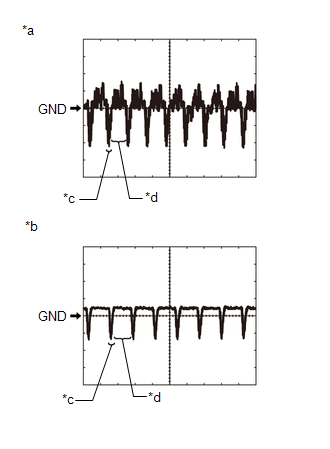
(a) Reference (Oscilloscope waveform):
|
*a |
Waveform 1 (camera lens not covered, displaying image) |
|
*b |
Waveform 2 (camera lens covered, blacking out screen) |
|
*c |
Synchronization Signal |
|
*d |
Video Waveform |
(1) Waveform 1 (camera lens is not covered, displaying an image)
|
Item |
Content |
|---|---|
|
Measurement terminal |
G2-28 (V+) - G2-29 (V-) |
|
Measurement setting |
200 mV/DIV., 50 μs./DIV. |
|
Condition |
Ignition switch ON, shift position in R, camera lens not covered, displaying image |
HINT:
- The video waveform changes according to the image sent by the rear television camera assembly.
- The video waveform is constantly output when the ignition switch is ACC.
(2) Waveform 2 (camera lens is covered, blacking out the screen)
|
Item |
Content |
|---|---|
|
Measurement terminal |
G2-28 (V+) - G2-29 (V-) |
|
Measurement setting |
200 mV/DIV., 50 μs./DIV. |
|
Condition |
Ignition switch ON, shift position in R, camera lens covered, blacking out screen |
HINT:
- The video waveform changes according to the image sent by the rear television camera assembly.
- The video waveform is constantly output when the ignition switch is ACC.
STEREO COMPONENT AMPLIFIER ASSEMBLY (for 9 Speakers)
|
Terminal No. (Symbol) |
Wiring Color |
Terminal Description |
Condition |
Specified Condition |
|---|---|---|---|---|
|
M2-1 (+B) - M2-3 (GND) |
L - W-B |
Power source (+B) |
Ignition switch off |
10.5 to 16 V*1 11 to 14 V*2 |
|
M2-3 (GND) - Body ground |
W-B - Body ground |
Ground |
Always |
Below 1 Ω |
|
M2-8 (WFL+) - M2-3 (GND) |
LA-Y - W-B |
Sound signal (Woofer) |
Audio system playing |
A waveform synchronized with sound signals is output |
|
M2-9 (FR+) - M2-3 (GND) |
LA-GR - W-B |
Sound signal (Front Right) |
Audio system playing |
A waveform synchronized with sound signals is output |
|
M2-10 (TWL+) - M2-3 (GND) |
LA-B - W-B |
Sound signal (Front Left) |
Audio system playing |
A waveform synchronized with sound signals is output |
|
M2-11 (RL+) - M2-3 (GND) |
LA-G - W-B |
Sound signal (Rear Left) |
Audio system playing |
A waveform synchronized with sound signals is output |
|
M2-12 (RR+) - M2-3 (GND) |
LA-R - W-B |
Sound signal (Rear Right) |
Audio system playing |
A waveform synchronized with sound signals is output |
|
M2-13 (TWR+) - M2-3 (GND) |
LA-BE - W-B |
Sound signal (Front Right) |
Audio system playing |
A waveform synchronized with sound signals is output |
|
M2-14 (FL+) - M2-3 (GND) |
LA-W - W-B |
Sound signal (Front Left) |
Audio system playing |
A waveform synchronized with sound signals is output |
|
M2-15 (WFR+) - M2-3 (GND) |
LA-R - W-B |
Sound signal (Woofer) |
Audio system playing |
A waveform synchronized with sound signals is output |
|
M2-16 (+B2) - M2-3 (GND) |
B - W-B |
Power source (+B2) |
Ignition switch off |
10.5 to 16 V*1 11 to 14 V*2 |
|
M2-18 (GND2) - Body ground |
W-B - Body ground |
Ground |
Always |
Below 1 Ω |
|
M2-23 (WFL-) - M2-3 (GND) |
LA-L - W-B |
Sound signal (Woofer) |
Audio system playing |
A waveform synchronized with sound signals is output |
|
M2-24 (FR-) - M2-3 (GND) |
LA-L - W-B |
Sound signal (Front Right) |
Audio system playing |
A waveform synchronized with sound signals is output |
|
M2-25 (TWL-) - M2-3 (GND) |
LA-LG - W-B |
Sound signal (Front Left) |
Audio system playing |
A waveform synchronized with sound signals is output |
|
M2-26 (RL-) - M2-3 (GND) |
LA-LG - W-B |
Sound signal (Rear Left) |
Audio system playing |
A waveform synchronized with sound signals is output |
|
M2-27 (RR-) - M2-3 (GND) |
LA-LG - W-B |
Sound signal (Rear Right) |
Audio system playing |
A waveform synchronized with sound signals is output |
|
M2-28 (TWR-) - M2-3 (GND) |
LA-GR - W-B |
Sound signal (Front Right) |
Audio system playing |
A waveform synchronized with sound signals is output |
|
M2-29 (FL-) - M2-3 (GND) |
LA-LG - W-B |
Sound signal (Front Left) |
Audio system playing |
A waveform synchronized with sound signals is output |
|
M2-30 (WFR-) - M2-3 (GND) |
LA-L - W-B |
Sound signal (Woofer) |
Audio system playing |
A waveform synchronized with sound signals is output |
|
M3-1 (MUTE) - M2-3 (GND) |
BE - W-B |
Mute signal |
Ignition switch ON Audio system playing |
2.0 V or higher |
|
Audio system changing modes |
Below 1 V |
|||
|
M3-2 (L-) - M2-3 (GND) |
G - W-B |
Sound signal (Left) |
Audio system playing |
A waveform synchronized with sound signals is output |
|
M3-3 (L+) - M2-3 (GND) |
B - W-B |
Sound signal (Left) |
Audio system playing |
A waveform synchronized with sound signals is output |
|
M3-4 (R-) - M2-3 (GND) |
R - W-B |
Sound signal (Right) |
Audio system playing |
A waveform synchronized with sound signals is output |
|
M3-5 (R+) - M2-3 (GND) |
W - W-B |
Sound signal (Right) |
Audio system playing |
A waveform synchronized with sound signals is output |
|
M3-6 (SLD) - Body ground |
Shielded - Body ground |
Shield ground |
Always |
Below 1 Ω |
|
M3-7 (TX-) |
W |
AVC-LAN communication signal |
- |
- |
|
M3-8 (TX+) |
B |
AVC-LAN communication signal |
- |
- |
|
M3-11 (SPD) - M2-3 (GND) |
L - W-B |
Vehicle speed signal |
Ignition switch ON Wheel being rotated |
Pulse generation |
|
M3-12 (ACC) - M2-3 (GND) |
LG - W-B |
Power source (ACC) |
Ignition switch off |
Below 1 V |
|
Ignition switch ACC |
10.5 to 16 V*1 11 to 14 V*2 |
|||
|
M3-14 (II1-) - M2-3 (GND) |
BR - W-B |
Voice signal |
Voice guidance sounding |
A waveform synchronized with voice signals is output |
|
M3-15 (II1+) - M2-3 (GND) |
Y - W-B |
Voice signal |
Voice guidance sounding |
A waveform synchronized with voice signals is output |
|
M3-18 (SLD1) - Body ground |
Shielded - Body ground |
Shield ground |
Always |
Below 1 Ω |
|
M3-24 (TMUT) - Body ground |
GR - Body ground |
Mute signal |
Ignition switch ON Audio system playing |
2.0 V or higher |
|
Emergency call mode |
Below 1 V |
- *1: w/ Stop and Start System
- *2: w/o Stop and Start System
DCM (TELEMATICS TRANSCEIVER) (w/ Manual [SOS] Switch)
Click here
![2020 - 2022 MY RAV4 RAV4 HV [10/2019 - 10/2022]; TELEMATICS: TELEMATICS SYSTEM: TERMINALS OF ECU](/t3Portal/stylegraphics/info.gif)
COMBINATION METER ASSEMBLY
Click here
|
|
|