| Last Modified: 01-30-2024 | 6.11:8.1.0 | Doc ID: RM100000001HH32 |
| Model Year Start: 2019 | Model: RAV4 HV | Prod Date Range: [02/2019 - ] |
| Title: A25A-FXS (FUEL): FUEL TANK (w/ Canister Pump Module): INSTALLATION; 2019 - 2024 MY RAV4 HV [02/2019 - ] | ||
INSTALLATION
PROCEDURE
1. INSTALL NO. 6 FUEL TANK CUSHION
(a) Install 5 new No. 6 fuel tank cushions to the fuel tank assembly.
2. INSTALL NO. 1 FUEL TANK PROTECTOR SUB-ASSEMBLY
(a) Attach the 2 claws and install the No. 1 fuel tank protector sub-assembly to the fuel tank assembly.
3. INSTALL NO. 2 FUEL TANK PROTECTOR
(a) Attach the 2 claws and install the No. 2 fuel tank protector to the fuel tank protector sub-assembly.
4. INSTALL FUEL TANK VENT HOSE SUB-ASSEMBLY
(a) Attach the 2 clamps and install the fuel tank vent hose sub-assembly to the fuel tank assembly.
(b) Connect the fuel tank vent hose sub-assembly to the fuel tank evaporation tube sub-assembly.
5. INSTALL FUEL TANK MAIN TUBE SUB-ASSEMBLY
(a) Attach the clamp and install the fuel tank main tube sub-assembly to the fuel tank assembly.
6. INSTALL FUEL TANK ASSEMBLY
CAUTION:
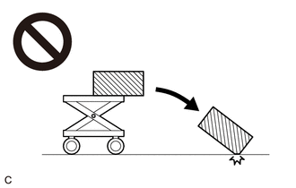
The fuel tank assembly is very heavy. Be sure to follow the procedure described in the repair manual, or the fuel tank assembly may fall off the engine lifter.

(a) Set the fuel tank assembly on an engine lifter.
NOTICE:
Using height adjustment attachments and plate lift attachments, keep the fuel tank assembly horizontal.
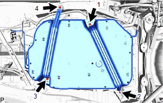
(b) Using the engine lifter, slowly raise the fuel tank assembly, and install the fuel tank assembly, fuel tank band and fuel tank band LH with the 4 bolts.
|
(c) Tighten the 4 bolts in the order shown in the illustration. Torque: 45 N·m {459 kgf·cm, 33 ft·lbf} NOTICE:
|
|
7. CONNECT FRONT LOWER NO. 1 FLOOR HEAT INSULATOR
(a) Attach the clip and connect the front lower No. 1 floor heat insulator to the fuel tank band sub-assembly.
8. CONNECT FUEL TANK FILLER PIPE SUB-ASSEMBLY
(a) Connect the fuel tank filler pipe sub-assembly to the fuel tank filler pipe assembly.
9. CONNECT FUEL TANK BREATHER TUBE
(a) Connect the fuel tank breather tube to the fuel tank filler pipe assembly.
10. CONNECT FUEL TANK MAIN TUBE SUB-ASSEMBLY
(a) Connect the fuel tank main tube sub-assembly to the fuel tube.
11. CONNECT FUEL TANK VENT HOSE SUB-ASSEMBLY
(a) Connect the fuel tank vent hose sub-assembly to the fuel tank solenoid main valve assembly.
12. INSTALL FRONT CENTER FLOOR COVER
(a) Attach the 2 clips and install the front center floor cover.
13. INSTALL FRONT FLOOR COVER LH
(a) Install the front floor cover LH to the body and tighten the 7 nuts.
(b) Attach the clip and install the 2 bolts and 4 screws.
Torque:
for bolt :
7.5 N·m {76 kgf·cm, 66 in·lbf}
14. INSTALL NO. 2 ENGINE UNDER COVER ASSEMBLY
15. INSTALL NO. 1 ENGINE UNDER COVER
16. INSTALL FRONT FENDER FRONT SPLASH SHIELD RH
17. INSTALL FRONT FENDER FRONT SPLASH SHIELD LH
18. ADD FUEL
19. INSTALL FUEL SUCTION WITH PUMP AND GAUGE TUBE ASSEMBLY
20. CONNECT CABLE TO NEGATIVE AUXILIARY BATTERY TERMINAL
NOTICE:
When disconnecting the cable, some systems need to be initialized after the cable is reconnected.
21. INSTALL BATTERY HOLE COVER
22. INSTALL REAR NO. 2 FLOOR BOARD
23. INSTALL DECK BOARD ASSEMBLY
|
|
|
![2019 - 2020 MY RAV4 HV [02/2019 - 08/2020]; A25A-FXS (FUEL): FUEL SYSTEM: PRECAUTION](/t3Portal/stylegraphics/info.gif)
