| Last Modified: 01-30-2024 | 6.11:8.1.0 | Doc ID: RM100000001HGJJ |
| Model Year Start: 2019 | Model: RAV4 | Prod Date Range: [02/2019 - 12/2021] |
| Title: FRONT SUSPENSION: FRONT SHOCK ABSORBER: INSTALLATION; 2019 - 2021 MY RAV4 RAV4 HV [02/2019 - 12/2021] | ||
INSTALLATION
CAUTION / NOTICE / HINT
HINT:
- Use the same procedure for the RH side and LH side.
- The following procedure is for the LH side.
PROCEDURE
1. INSTALL SST
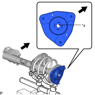
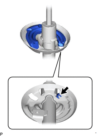
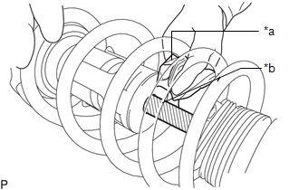
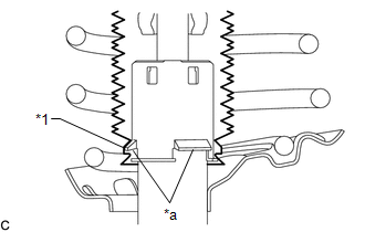
(a) Align the cutout on end of the shock rod of the front shock absorber assembly LH with the installation position.
NOTICE:
Be sure to install the part so that the cutout on the front suspension support sub-assembly LH and the cutout on the shock rod end are aligned.
|
*a |
Cutout |

|
Vehicle Exterior |
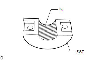
(b) Install SST (09727-58100) and SST (09727-58130) to the front shock absorber assembly LH.
SST: 09727-58100
SST: 09727-58130
SST: 09727-58010
09727-58030
|
*1 |
Front Shock Absorber Assembly LH |
*2 |
Shock Absorber Outer Shell |
|
*a |
Turn |
*b |
Hold |
|
*c |
Fixing Nut |
*d |
Bolt |
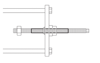
NOTICE:
Apply molybdenum grease to the bolt (area with diagonal lines) of SST (09727-58010).

|
Application Area |
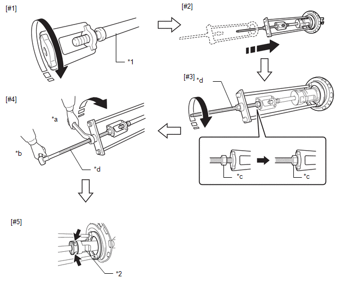
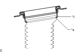
(1) Install SST (09727-58030) to the end of the shock rod of the front shock absorber assembly LH.[#1]
(2) Install SST (09727-58010) to the front shock absorber assembly LH.[#2]
NOTICE:
Take due care when installing SST (09727-58010) to ensure the shock rod is not damaged.
(3) Secure the SST (09727-58010) bolt and SST (09727-58030) with the fixing nut.[#3]
(4) After securing the SST (09727-58010) bolt, rotate the nut clockwise.[#4]
HINT:
Extend the shock rod to its maximum length to install SST (09727-58100) and SST (09727-58130).
(5) Using a piece of cloth, etc., clean the shock rod and remove any foreign matter and oil.
NOTICE:
Thoroughly clean the shock rod to prevent damage to the shock rod due to contact of foreign matter.
|
(6) Clean the surface of SST (09727-58130) to which the front shock absorber assembly LH is installed and remove any foreign matter and oil. NOTICE: Thoroughly clean the installation surface to prevent damage to the shock rod due to contact of foreign matter. |
|
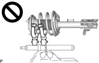
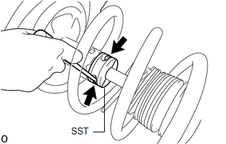
(7) Using a long ball hexagon 5, install SST (09727-58100) and SST (09727-58130) to the shock rod.[#5]
NOTICE:
Before installing, check the position of the cutout on end of the shock rod.
HINT:
Install SST (09727-58100) and SST (09727-58130) to the base of the shock rod and check that SST (09727-58100) and SST (09727-58130) are securing the shock rod.
(8) After securing the SST (09727-58010) bolt, rotate the nut counterclockwise.
(9) Check that the shock rod and SST (09727-58030) have become free before releasing the fixing nut and removing SST (09727-58010) from the shock rod.
NOTICE:
Take due care when removing SST (09727-58010) to ensure the shock rod is not damaged.
(10) Remove SST (09727-58030) from the end of the shock rod.
(11) Using a piece of cloth, etc., clean the end of the shock rod threads and remove any foreign matter and oil.
2. INSTALL FRONT LOWER COIL SPRING INSULATOR
(a) Install the front lower coil spring insulator to the front shock absorber assembly.
NOTICE:
When installing the front lower coil spring insulator, insert the positioning pin of the spring seat into the hole of the front lower coil spring insulator.
|
|
Positioning Pin |
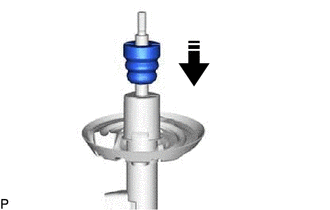
3. INSTALL FRONT SPRING BUMPER
|
(a) Install the front spring bumper to the front shock absorber assembly. NOTICE:
|
|
4. INSTALL FRONT COIL SPRING
|
(a) Secure SST in a vise. SST: 09727-30022 09727-00010 09727-00031 SST: 09727-00051 |
|
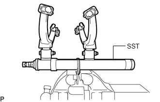
(b) Attach the hooks of each SST arm across the diameter of the coil spring.
CAUTION:
-
Make sure that the hooks are securely attached to the coil spring.
- If a hook disengages from the coil spring, the coil spring may fly out, resulting in injury.
-
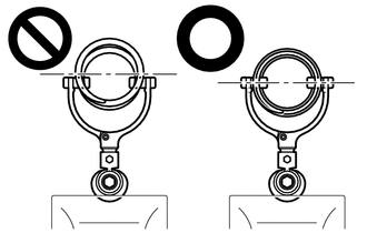
Make sure that the hooks of the upper and lower SST arms are attached to the coil spring so that the distance between the hooks is as large as possible.
- If a hook disengages from the coil spring, the coil spring may fly out, resulting in injury.
-
Make sure that the arms of SST are parallel and the number of coils between the arms is the same on each side.
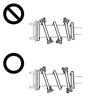
- If a hook disengages from the coil spring, the coil spring may fly out, resulting in injury.
(c) Install the stopper pins to the hooks of SST.
CAUTION:
- Make sure that the stopper pins are installed securely.
- If a hook disengages from the coil spring, the coil spring may fly out, resulting in injury.
(d) Using SST, compress the coil spring.
SST: 09727-00110
CAUTION:
-
If the coil spring starts to bow out while using SST, stop immediately and reattach SST correctly.
- If a hook disengages from the coil spring, the coil spring may fly out, resulting in injury.
-
Do not compress the coil spring to the point where the coils touch each other.
- If a hook disengages from the coil spring, the coil spring may fly out, resulting in injury.
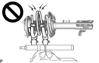
-
Do not use an impact wrench.
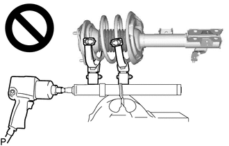
- If an impact wrench is used, the threads of SST may be damaged, or sudden compression of the coil spring may cause a hook to disengage and the coil spring to fly out, resulting in injury.
-
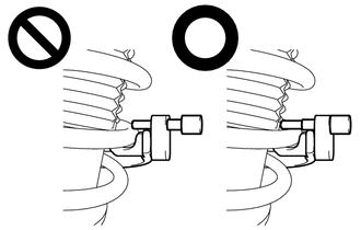
If a stopper pin touches the coil spring while using SST, remove the stopper pin and continue with the procedure.
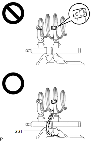
- If a stopper pin is removed, install a coil spring stopper belt as shown in the illustration.
- If a hook disengages from the coil spring, the coil spring may fly out, resulting in injury.
|
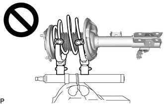
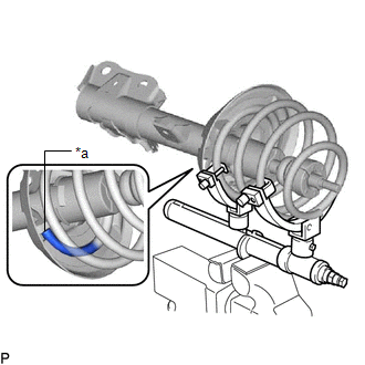
(e) Align the end of the front coil spring with the flange of the front lower coil spring insulator and install the front coil spring. NOTICE: Make sure to fit the end of the front coil spring that has the larger diameter into the depression of the front lower coil spring insulator. |
|
5. INSTALL STRUT MOUNTING BEARING
|
(a) Install the strut mounting bearing to the front No. 1 shock absorber dust cover. NOTICE: Make sure that the top end of the front No. 1 shock absorber dust cover and strut mounting bearing are securely attached. |
|
6. INSTALL FRONT UPPER COIL SPRING INSULATOR
(a) Install the front upper coil spring insulator to the strut mounting bearing.
7. INSTALL STRUT MOUNTING BEARING WITH DUST COVER
(a) Install the strut mounting bearing with dust cover to the front shock absorber assembly.
8. INSTALL FRONT SUSPENSION SUPPORT SUB-ASSEMBLY
(a) Install the front suspension support sub-assembly as shown in the illustration.
NOTICE:
Check that the slot on the piston rod and the slot on the front suspension support sub-assembly are aligned.

|
*a |
Slot |
|
|
Outside of the Vehicle |
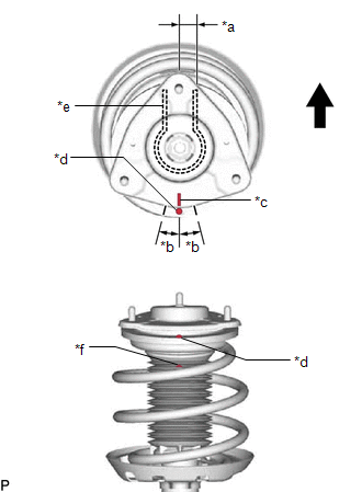
(b) Align the alignment mark of the front suspension support sub-assembly with the front shock absorber lower bracket as shown in the illustration.
NOTICE:
Make sure to install the front suspension support sub-assembly so that the alignment mark of the front suspension support sub-assembly is aligned within +/- 3° of the center of the front shock absorber lower bracket.
|
*a |
0° +/- 3° |
|
*b |
15° |
|
*c |
Guide Line of Front Suspension Support Sub-assembly |
|
*d |
Alignment Mark of Strut Mounting Bearing |
|
*e |
Front Shock Absorber Lower Bracket |
|
*f |
Arrow of Shock Absorber Dust Cover |
|
|
Outside of the Vehicle |
(c) Align the alignment mark of the strut mounting bearing with the guide line of the front suspension support sub-assembly as shown in the illustration.
NOTICE:
Make sure to install the strut mounting bearing so that the alignment mark of the strut mounting bearing is aligned within +/- 15° of the guide line of the front suspension support sub-assembly.
(d) Align the arrow of the shock absorber dust cover with the alignment mark of the strut mounting bearing as shown in the illustration.
9. TEMPORARILY TIGHTEN FRONT SUPPORT TO FRONT SHOCK ABSORBER NUT
(a) Temporarily tighten a new front support to front shock absorber nut.
(b) Remove SST from the front coil spring.
NOTICE:
Do not use an impact wrench. It will damage SST.
|
(c) Fold back the No. 1 front shock absorber dust cover LH and then use a long ball hexagon 5 to remove SST (09727-58100) and SST (09727-58130) from the front shock absorber assembly LH. NOTICE:
|
|
|
(d) Using a piece of cloth, etc., clean the shock rod of the front shock absorber assembly LH and remove any foreign matter and oil. NOTICE: Thoroughly clean the shock rod to prevent damage to the front shock absorber assembly LH due to contact of foreign matter. |
|
10. CONNECT FRONT NO. 1 SHOCK ABSORBER DUST COVER
|
(a) Connect the end of the front No. 1 shock absorber dust cover with the claws of the front shock absorber assembly. NOTICE:
|
|
11. INSTALL FRONT SHOCK ABSORBER WITH COIL SPRING
(a) Install the front shock absorber with coil spring (upper side) with the 3 nuts.
Torque:
50 N·m {510 kgf·cm, 37 ft·lbf}
(b) Install the front shock absorber with coil spring (lower side) to the steering knuckle with the 2 bolts and 2 nuts.
Torque:
290 N·m {2957 kgf·cm, 214 ft·lbf}
NOTICE:
- When installing the nuts, keep the bolts from rotating.
- Do not apply lubricants to the steering knuckle and shock absorber contact surfaces.
HINT:
The bolts can be installed in either direction, however, make sure that they are both installed in the same direction.
12. FULLY TIGHTEN FRONT SUPPORT TO FRONT SHOCK ABSORBER NUT
(a) Fully tighten the front support to front shock absorber nut.
Torque:
47 N·m {479 kgf·cm, 35 ft·lbf}
NOTICE:
Perform this step only when the front shock absorber with coil spring has been disassembled.
13. INSTALL FRONT SPEED SENSOR
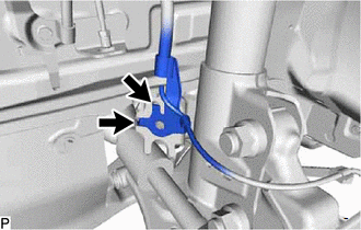
(a) Engage the 2 hooks to install the front speed sensor clamp bracket.
NOTICE:
Do not twist the front speed sensor when installing it.
|
|
Hook |
|
(b) Install the front speed sensor and front flexible hose to the front shock absorber assembly with the bolt. Torque: 29 N·m {296 kgf·cm, 21 ft·lbf} NOTICE: Do not twist the front flexible hose when installing it. |
|
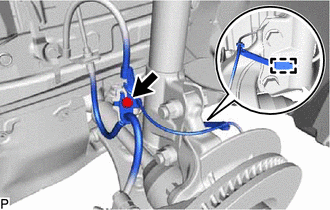
(c) Engage the clamp.
NOTICE:
Do not twist the front speed sensor when installing it.
14. INSTALL FRONT STABILIZER LINK ASSEMBLY
(a) Install the front stabilizer link assembly to the front shock absorber assembly with the nut.
Torque:
74 N·m {755 kgf·cm, 55 ft·lbf}
HINT:
If the ball joint turns together with the nut, use a 6 mm hexagon socket wrench to hold the stud bolt.
15. INSTALL COWL VENTILATOR PANEL SUB-ASSEMBLY
Click here
![2019 - 2020 MY RAV4 HV [02/2019 - 08/2020]; HEATING / AIR CONDITIONING: AIR CONDITIONING UNIT (for A25A-FXS): INSTALLATION+](/t3Portal/stylegraphics/info.gif)
16. INSTALL COWL VENTILATOR SPLASH SHIELD
Click here
17. INSTALL WINDSHIELD WIPER MOTOR AND LINK ASSEMBLY
Click here
18. INSTALL FRONT WHEEL
Click here
19. INSPECT AND ADJUST FRONT WHEEL ALIGNMENT
Click here
20. PERFORM INITIALIZATION
Click here
|
|
|